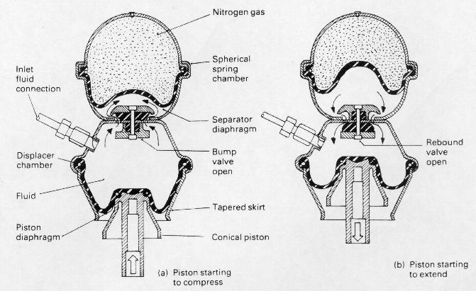
The spring unit is comprised of a nitrogen filled spherical spring chamber welded to a double conical shaped displacement chamber.
A hydraulic damper in the form of a pair of rubber compression blocks separates both spherical spring and displacer chambers, its function being to control the flow of fluid as it passes to and fro between the two chambers.
The displacer chamber is sealed at its lower end by a load absorbing nylon reinforced rubber diaphragm (piston diaphragm) which rolls between the conical piston and the tapered displacer chamber skirt as the suspension deflects up and down when the wheels pass over any irregularities on the road surface.
Within the spherical chamber is a butyl-rubber diaphragm (separator diaphragm) which separates the sphere into a nitrogen charged (17.5 bars) upper region (the spring media) which is sealed for life, and the lower region which is filled with fluid.
Initially fluid is pumped into the the displacer chamber until it reaches the nitrogen charging pressure. Then it will compress and lift the separator diaphragm off the bottom of the sphere. Since the gas and fluid pressures are equal, the separator diaphragm is not subjected to heavy loads, in fact it only functions as as a flexible wall to keep the gas and fluid apart.
A water based fluid containing 50% industial alcohol and a small percentage of anti-corrosion additive is pumped into the system to a pressure of 23 bars with the car in a unladen state, this being the condition in which the car's body to ground height is checked.
One advantage in using the rolling diaphragm type of displacer is that a water based fluid can be utilised as opposed to an oil which would not have such stable viscosity characteristics.
The effective area of the piston compressing the fluid is that projected area of the displacer diaphragm which is not supported by the internal tapered skirt of the displacer chamber. Therefore, as load on the displacer piston increases, and the piston is pushed further into the chamber, less of the displacer diaphragm will be supported by the chamber's skirt and more will form part of the projected effective piston area.
The consequence of the diaphragm piston pushing up within the displacer chamber is that the load bearing area of the piston is increased due to the diaphragm rolling away from its supporting tapered chamber skirt. As a result the resistance offered by the fluid against the the upward movement of the piston rises.
In other words, due to the tapered chamber's skirt, the spring rate (stiffness) increases in proportion to the spring's deflection.
The progressive action of the rubber valve between the two chambers provides
for a measure of damping which slows down bump and rebound movements caused
by the impact of the tyre on very bumpy roads.