A recent call from a member in New England concerned the steering wheel hub that was now making heavy contact with the plastic cowling of his 1971 MGB. He said the column coming through the scuttle (firewall) to the universal joint was fine, but that it appeared that the steering end of the column was perhaps collapsing - and I think he was correct!
The two pieces of the upper steering column are "pinned" together, the upper sliding within the lower section, by a small amount of plastic material which was poured in by the manufacturer, and this upper column area is then surrounded by a supporting section of a heavy mesh-like metal sleeve, all of which makes up the collapsible section of the steering column.
The whole of this section is normally a long-lived unit, giving no problem during the life of the car, but like many things in life, the average owner can often overcome the best planned design of the factory. I have seen many drivers use the steering wheel as a fulcrum point, as they swing themselves into the driver's seat. I have also seen so-called qualified mechanics hammer on the steering column itself when attempting to remove a steering wheel. Both of these actions will put heavy stress on the plastic locking 'pins' that connect the two pieces of the upper steering column assembly, the eventual result of which is a broken piece of plastic and an upper steering column that slowly starts to move forward!
The alternative to the first action is to sit down on the driver's seat and then swing your legs into the cockpit, never putting added weight onto the steering wheel and/or steering column. And why not use a simple steering wheel "puller" tool to remove the steering wheel? Both of these actions will be beneficial towards increasing the life of that small ball-bearing assembly at the top of the steering column.
There are several things that an owner can do to resolve the initial concern expressed by our member. First, you can live with what you have and hope that things will not get worse. Or, you can replace the steering column with a good one, one that has not started to collapse. Or, you can attempt a repair that is slightly involved but which most likely will be just as secure as the original plastic 'pins'.
Following the Haynes Manual, remove the steering column from the MGB. After separating the inner column from the outer, you will see four small opposing holes in the outer column and two large circular grooves on the inner column - all filled with plastic material.
Remove the plastic material, reposition the two pieces of the column to their proper position and drill two 1.8" holes through the original holes in the outer column and through the inner column. Now insert 1/8" aluminium cotter pins through these two holes and you will have a secure upper column, and one that will collapse as designed in an accident situation.
DO NOT use steel cotter pins or bolts as either approach will negate the collapsible feature of the steering column. To be on the safe side, you might consider using just one of the aluminium cotter pins. Best bet though, is to install a replacement steering column unit that you know is in its original, uncollapsed condition.
RUST COLLECTORS
Two major areas for the formation of rust (and holes) on the MGB are at the top of the reinforcing box section at the rear of each front wheel arch, and behind the splash panel to the rear of the front wheel.
The top of the reinforcement box section is a very convenient place for road salt, dirt, and wet mud or whatever to collect. Over time this will build up and create a Swiss cheese pattern of rusted metal, even affecting the top of the fender, so the owner will wish to keep this area clean and rust-proofed with some type of preventive material.
|
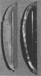
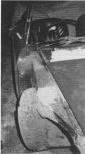
Rust-through compromises the ability of the splash panel to keep the dirt and damp out of the lower front fender area. The difference in the new panel and the one it is replacing is apparent at the bottom as shown in the photo left. The panel is seen in situ in the accompanying photo right. |
|
The splash panel is secured by 4-6 bolts and seals, supposedly, to the inner portion of the front wing with a rubber seal which supposedly prevents dirt, sand and water from entering the enclosed area.
When the splash panel is removed, one can see the forward section of the rocker panel and the inner rear section of the front wing, with probably a collection of sand and dirt along the lower sides. When the car is driven in the rain, water will pass through the rubber seal area and dampen the collection of sand and dirt, all of which will cause rust to eat through the front of the rocker panel and the lower rear area of the front wing.
The only solution is, after removing the splash panel, is to take a water hose and wash away all of the foreign material, most of which will exit at the vertical seam where the lower rear of the wing meets the outer portion of the rocker panel. While the similar vertical seam where the rocker panel meets the rear wing is meant to be sealed, the front seam is designed to remain open, hoping that the material that enters the splash panel will eventually exit at the open front seal area. But it seldom does, remaining instead in the enclosed area to create rust-through in these panels.
If on inspection of this area you find excessive rust-through, the only alternative is replacement of the panels. If there is just a collection of sand and dirt, wash this debris away and then apply a liberal coating of Waxoyl. Then, after the splash panel is reattached, you can more securely seal the area of the rubber seal by applying a coating of RTV silicone sealant where the rubber panel seal adjoins the inner wing area.
Now a letter from Michigan....
Dear Bob,
I have a 1965 MGB and it is hesitating on acceleration. I have checked the camshaft valve timing and function, replaced the ignition several times using Lucas Electronic ignition, changed to a higher ignition coil, checked vacuum, and mechanical advance, changed the plugs and distributor and also checked that I have the correct LU distributor and vacuum advance. The only clue I have is that the vacuum advance appeared a bit excessive, more than 45 degrees maximum. During the setting and timing, I tried disconnecting the vacuum advance, reducing the advance and the hesitancy was dramatically improved, though it still doesn't run or respond as well as my 18G MGB engined TD. Should I replace the distributor again? Any other ideas would be welcomed to solve the problem.
Vance Smith,
Muskegon, Michigan
Dear Vance,
Thanks for your query and the stamped envelope! You did not mention what model distributor you are using, nor the model of vacuum advance or even what timing you are setting so the answer to your problem may be a bit difficult, to say the least. I myself have a '67 MGB GT that uses a similar unit to what you should be using and have had no problems whatsoever, although that's little consolation to you!
You should be using the Lucas 25D model that would be using a distributor cam that is somewhere in the neighbourhood of 10 to 14 degrees. The variances would be minimal, and a vacuum unit that should have markings near the vacuum pipe something like 5-13-10. The '5' indicates where the vacuum unit starts to function, the '13' at which maximum advance occurs and the '10' indicated the maximum advance unit is working correctly. Remember, the mechanical advance only works on acceleration and the vacuum unit works only while cruising at a steady speed on a light throttle opening.
You should also be using the standard 12 volt coil or the higher/stronger unit called the Sports Coil which also operates on the 12 volt system. Your total advance should only be somewhere in the neighbourhood of 25 to 30 degrees at 3500-4000 rpm or thereabouts. Which leads me to ask - have you checked your dwell? It should be at 60 degrees, + or - 3 degrees or so, and should not vary as you change speeds. If it wobbes in excess of 2-3 degree, you have an excessively worn bush(s) in your distributor shaft and the unit should be replaced or repaired. Set your timing by strobe light at 20 degrees before TDC at 1000 engine rpm, then reset your idle rpm to about 800-850 rpm. Assuming your timing gears are set correctly and your carburetors are adjusted both for fuel level and mixture strength, you should have no hesitation upon acceleration at any speed.
For all purposes, almost all of the Lucas 25D model distributors are identical, with the variance being in the vacuum unit. Your original distributor would most likely have had the Lucas number 41288 stamped on the side and the vacuum unit would have shown the Lucas number 54411985 stamped near the tip. But you can satisfactorily use just about any vacuum unit as fitted to the 'B engine from 1962-'71 on engines using the HS4 carburetors - but NOT the HIF vacuum units which have a flat face with the connector port offset to the side.
Should you wish to have your unit tested then I seem to recall that John Twist at University Motors in Ada, Michigan has a testing machine.
BURNT OUT!
A Register member recently called to ask what to do about a failed illumination bulb in one of the rocker switches in his 1977 MGB. These small bulbs rarely fail, but when they do, they are available from our major suppliers (e.g. Moss #170-160). To obtain access to the bulb use a small pick or knife blade to remove the plastic lettering portion of the switch and you will see the bulb. Slip a small piece of vacuum hose tightly over the bulb and you will then easily both remove and replace the bulb. This same bulb by the way is also used on the brake warning check lamp on the 1968-'76 MGBs.
MOUNTING THE MOTOR
From 1975 to 1980 all MGBs utilized a round rubber front engine mount which was interchangeable left or right. After an extended time, or many miles of use, this rubber mount will either sag downwards to a considerable degree, or break away from one of its metal mounting plates. Both situations requiring that the mount needs to be replaced, an aggravating job at the minimum!
An improved engine mount for any of these MGBs is the rubber mount for the MGB GT V8 model which is the same shape and dimensions, but which is manufactured with a denser (harder) rubber composition. This will not deform as compared to the standard MGB rubber mount and is available under the factory part number of BHH1318.
When installing either of these rubber mounts, ensure the offset stud which attaches through the frame rail metal mount is to the lower position. Also when inspecting your rubber mounts, take a long look at the metal mounting bracket which attached to the front engine mounting plate to see if there are any cracks where the metal mounting plate makes its 90 degree bend. Any crack requires immediate repair or, preferably, replacement.
Visit the NAMGBR pages
 Back to the News content
![[Copyright/Credits]](../pics/mini-copyright.gif)
![[Home]](../pics/mini-home.gif)
![[Information]](../pics/mini-info.gif)
![[Feedback]](../pics/mini-mail.gif)