
Image courtesy of Gary Tonge
Image courtesy of Gary
Tonge
MGF FAQ Part II
Version 4 .6 - 18th February 2000
This site is entirely independent of the Rover Car Company and MG Cars. It
is compiled by enthusiastic owners and represents additional advice for owners.
It is not a substitute for the official MGF handbook and no responsibility
is accepted for any loss or damage.
Click the relevant topic to quickly jump to that area.
You have up to 10 months to extend your Rover 12 month warranty - one or two people who have had problems with their cars have had their warranty extended free of charge when they have experienced inconvenience so it may be worth waiting six months or so before extending the warrantee if you intend to do so.
The
MGF's 1st birthday party
Large promotional
type pictures
The
Cambridge & District F Image Gallery
Casey's
Pictures
MGF
Cartoons
Carsource
1.8i
Irish
Review
Views from
a MG site
Daily Telegraph
Review of the MGF
race car
Sydney
Morning Herald Review
Trident Garages
Clive Sutton
Swain & Jones
Edwards
AppleYard Leeds
Rover MGF page
Rover Thailand
Page
Dirk
John Thomas
Olaf
Anell
Caroline
Hamant
Kumar
Martin
Woods
Richard
Osborne
Scarlet
Fever
Rob Bell
Adam
Diggins
Hazel
includes Munich MG Meets
Richard Eaton includes
MGF Web Ring
John Houston - MGF Scotland
Erik
Neil
Sean
Mike Satur - interior
designers and manufacturers
Newton Commercial
Accessories
MotoBuild Web Site
Click here to buy MG car parts online
from Unipart
BBR.-GTi MGF
Conversions
Chrome Design
Paul Sharpes MGF
Accessories
The MG Car
Club
COLPUC
The MG Car
Club F Register
The MG Cars
Enthusiasts Club MGF Page
Autolist
2nd hand MGF's for sale in the UK
SuperCars
Web Site - MGF page
MGF
Events List
MGF
Bulletin/Chat Board - come and say hello to fellow enthusiasts
TechSpeed - runners in the MGF
Cup
the F'ers Gallery and MG Dealer Guide
MG has been advised that the Alarm and Immobiliser system as fitted to current MGF models has now been approved to Thatcham Category 2 Level. This information has been relayed by Thatcham to all the British insurance companies subscribing to their services. There is a Thatcham help line for MG and Rover customers on 0990 502006.
Insurance prices as of November 1996 varied between £270 and £430, so it pays to shop around. Check if you get discount for being a member of the MG Car Club (1st year membership free with a new MGF). Also check the amount of excess you will have to pay.
If you have a tracker fitted they will send you a list of insurance companies who give a discount for tracker fitted cars - Tracker Freephone 0500 090909
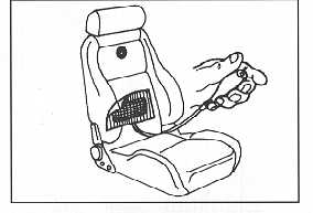
The following is for information only. From a safety point of view you should get your MGF checked if the SRS warning light comes on, as per the manual.
If you find that your SRS warning light comes on and stays on, check the wiring to the 'explosive' seat belt restraints. The wiring is under the seat and comes up from under the carpet and goes into the seat itself. The position of the wiring means that it can easily get trapped under a metal bar that rests on the carpet. Moving the seat back or forward can then pull the connector apart.
First release the clips that hold the lower rear end of the soft-top to the back parcel shelf. Raise the rear of the soft top toward the front of the car. Then remove all the parcel shelf trim and layers of sound insulation to reveal the engine compartment cover and undo about 10 small bolts that hold the cover down, lift it off to reveal the engine in all its glory.
For further details see the section on Fitting a K&N Filter
While the engine cover is off you can change the oil - there's a proper filler cap on top of the engine and you can pour oil in there far more easily than the proper way which is in effect 'down the dipstick tube' or you can drain the oil and access the filter from the side, just in front of the rear right hand side wheel.
Remove the bumper (two screws each end , five across the top and two bolts behind the indicators) then undo the two 10mm bolts and release the lamp assembly from the side and lower retaining clips. Once out the lens is retained to the reflector by six clips.
NB: Specs change from country to country, this comparison is based on the UK specs July 1997
The 1.8i has a maximum power of 120Ps at 5500 rpm, the VVC achieves 145Ps at 7000 rpm (ie the VVC needs much higher revs to get the extra pwr). This is a 17% difference
The 1.8i has max torque of 165 Nm at 3000 rpm, the VVC has 174 NM at 4500 rpm ie 5% difference
If you compare the perfomance by graphs, up to 5000 rpm, the 1.8i and VVC have identical power bands, after this the 1.8i goes down, the VVC keeps going up.
Similar with the torque, up to 5000 rpm there's little in it, the VVC dies off after the 1.8i does
0-60 manufacturers time has the 1.8i at 8.5, the VVC at 7.0
TopGear gives 0-60 times of 8.8 sec for 1.8i and 8.4 for VVC
Autocar gives 0-60 times of 8.7sec for 1.8i and 7.6sec for VVC.
John Thomas has graphed rpm/mph/gear for 1.8i and the VVC
There has been one known case of somebody purchasing a second hand MGF VVC, which turned out to be a 1.8 mpi. So check the following out that a VVC should have.
1. VVC alloys
2. ABS unit fitted under front bonnet (standard on 1.8i from early 199, standard VVC from day one)
3. Half leather seats
4. VVC plenium chamber (seen through the engine bay grill on opening the boot, on the right hand side)
5. Rev counter red lined to 7250 rpm.
6. VIN number- ass seen through the windscreen on the left of the vehicle. The eighth letter should be the letter 'T' and NOT the letter 'G' [The VIN Number].
In view of all the recent comments re: front tyre wear etc it would seem
imperative that the alignment of the front sub frame is absolutely spot on. Any
"bump" that has required a new bumper, front wings etc is likely to
have distorted the body enough that the sub frame may not align properly and
there are likely to be all sorts of alignment/tracking/tyre wear in the future .
Personally I would steer clear of any car with evidence of an accident not
matter how inviting the price.
I have driven my 1.8i for 12,000 miles, and a VVC for 600 miles. In my opinion, the VVC revs more freely, has a raspier engine noise, and seems a little quicker, but there's not much in it. I find the PAS makes the VVC seem more twitchy, compared the non-PAS 1.8i. I also find that the 1.8i picks up better than the VVC, the VVC seems to exhibit a kind of 'turbo-lag' at lower revs. Greg Hilton
I've completed just short of 12,000 miles in both. First of all both engines take a very long time to run in. In fact I feel that they both took at least 10,000 miles. The 1.8i, by the time I traded it in, was much quicker to drive than my dealers demonstrator VVC. Its pull was good especially up the rev range. Where it was possibly still lacking was low down, especially if you were maybe one gear higher than optimum. If you floored it at 30 in 3rd, the response wasn't really electric. If you were in 2nd it was great.In terms of entertaining B road driving, the 1.8i was more than enough for me. It was possible to oversteer on the exit to bends in both 2nd and 3rd, especially on a poor surface or in the wet.
The first thing about the VVC is that the gearing is shorter. This definitely makes motor way driving a shade noisier. The VVC also makes a different, slightly gruffer, noise. It's not a TVR but if you're in a garage it is obvious. Once the VVC was run past around 6,000 miles I'm sure it felt a bit quicker than the 1.8i. Its not that the 1.8i can't be made to be almost as fast as the VVC in normal driving, its just that you don't have to work or think so hard to achieve it. Especially on B roads, I found that I could drop from 4th to 3rd for a bend and still punch out: in the 1.8i I'd have wanted 2nd for the exit but the overall result would have been similar. Basically both cars have limits that I only ever access because I'm a *bad* driver. If I was smoother, picking better lines etc, I wouldn't have lost as much speed in the bends and wouldn't have needed to test adhesion limits on the exit.
Obviously you can't often drive this way on public roads either. On the motor way there is definitely more punch in the VVC: it pulls in 5th much better but again this could be explained mostly with the gearing difference. The extra rev-range (basically there is no discernible drop in power or acceleration right up to the vicious rev limiter) is great but sucks petrol at a frightening rate. Drive to the limit often and you'll see sub 24 MPG figures as opposed to my average of 32 and best of 42. Graeme Bishko
The Steptronic was launched in October 1999. It will be a standalone model, rather than just an option on the 1.8i model (which engine it uses). Price is 20495 GBP on the road with standard features including new audio system with 6 speakers, ABS, Power Steering, unique alloy wheel design etc. It uses the CVT gearbox used previously with the K series engine, however unique to the MGF is its 6 speed manual capability, this can be switched to and then gears can be selected by up/down gearshift buttons mounted on the steering wheel (F1 style).
This site has info on the steptronic http://members.tripod.com/cjghome/mgf.htm
It is possible to install a handsfree car phone kit into the MGF, and it's perfectly usable, until your driving over 30mph with the roof down.
There are four components.
You can also install a Nokia Car Kit (CARK91) into the MGF without drilling anything.
Use a "Dash Mount" bracket to take the phone cradle and (on the reverse)speaker unit. The bracket is manufactured to many makes of car but they do manufacture one specifically for the MGF.
The bracket fits into the edge of the central console, and is held in place by the plate being trapped by the console.
Instructions for fitting are simple -
1. Remove the centre console housing by pulling backwards from the gear lever end and unclipping accordingly.
2. Lever out the fascia trim panel to the left of the heater controls and switches.
3. Locate the bracket in the recess and replace the fascia trim and console panel to secure.
NB Later models enable the bracket to merely be pushed in between the console edge and fascia at a slightly lower level where it naturally grips in place.
The Item is Code 71633.
Available from
Connoisseur Products Ltd.Tel 0181-948-0067, Fax 0181-948-0068
Cost £20
The use of this bracket has made installation considerably easier, with the bonus of no holes drilled into the dashboard at all. (No I don't work for the company).
The aerial for the locking and security transceiver can be better positioned
There is a triangular panel which houses the footwell light in the passenger (left hand) side of the car which is secured by two cross head self tapping screws.
Remove this panel and just behind it you will see a part of the wiring loom and you should see an ultra thin bright yellow wire that is probably coiled and taped to the loom.
Remove tape and straighten this wire, you will see it only connected at one end to black connector block just behind the dash.
Lay the yellow wire in as straight a position as you can behind the footwell light panel, I found it went towards the front of the car behind a couple of large wire bundles and rested quite nicely in an existing cable support.
Try your blipper and adjust as required, when satisfied with the results use a small piece of insulating tape to secure the cable in the desired position, there are plenty of bits of wiring to tape to.
Check your blipper again, and replace the footwell light panel.
Another way to increase the range of the blipper is to hold the blipper against a piece of bare skin on your body (head / hand etc) and press the button.... adds a good five feet or so to the range.
Problem:- Rapid or sudden application and release of the brake pedal (Emergency stop, autotesting etc) causes the ratchet mechanism in the brake light switch to close up a notch or two, causing the brake lights to be sensitive to bumps or, at worst, on all the time.
The solution is to reset the ratchet as discussed below
The switch is situated under the dash, just above and behind the pivot point of the brake pedal. It is a pig to get at and is released by twisting (if I remember correctly). The ratchet can also be reset by depressing the brake pedal and at the same time pulling the plunger on the switch out.
All you need to do is either remove the switch or while you have your head in the footwell, give the plunger of the switch a VERY hard tug. This pulls the ratchet out and the next operation of the pedal sets the switch clearance up.
If the above fails to work then there is a MG technical bulletin on the
same problem,
it seems MG have designed a new switch, the affected Range = All vehicles upto
VIN 036126
old part number = XKB 100080; new part number=XKB 10003
This is designed to fix the problem once and for all, the new switch is not self
adjusting, but uses a set of washers held on with a nut to set the correct
level.
The manual is a normal Rover/MG part, and can be ordered from any parts department - just quote the product code. This is: Part No. RCL 0051 ENG.
The ENG bit is the language so your dealer may be able to try others e.g DEU is the German version.
 If you feel the seats in your
MGF don't support you enough, you can buy an inflatable pad to fit in the
lumbar of the seat. The pad is invisible when installed and can be done in
5 seconds with no tools or damage to the seats! You simply pull the lower
seat upright forward a little and slide the flat, uninflated pad behind it.
All that remains is a small inflation pump that rests next to the seat and
allows you to pump up or deflate the pad.
If you feel the seats in your
MGF don't support you enough, you can buy an inflatable pad to fit in the
lumbar of the seat. The pad is invisible when installed and can be done in
5 seconds with no tools or damage to the seats! You simply pull the lower
seat upright forward a little and slide the flat, uninflated pad behind it.
All that remains is a small inflation pump that rests next to the seat and
allows you to pump up or deflate the pad.
Because you install it yourself, you can adjust the height at which the support is provided, not many built in lumbar supports provide this level of adjustment!
The pads are made by the racing seat manufacturer Corbeau, and you can buy them by mail order or in person from RMP Motorsport . Each pad costs £24.50 plus VAT and postage - total around £39 and I've had one in my drivers seat for over six months with no problems.
RMP Motorsport Parts can be contacted on: 07000 747 77333 or 0181 803 4355
There is another lumbar support in their catalogue, made by Sparco, but you want the Corbeau one. Their shop is in North London very close to White Hart Lane football stadium.
The MGOC was formed in 1973 to serve the growing needs of the MG enthusiast. Over the last 24 years the Club has concentrated on making it easier, cheaper and more enjoyable to own an MG. Membership has grown to 50,000 making it the world's largest single marque car club.
The MGOC offers its members many benefits including:-
The M.G. Car Club is an international club based in the heart of M.G. country - Abingdon in Oxfordshire. Since formation in 1930 by John Thornley O.B.E., the Club has provided high quality support and backing to all its members. The Club is unique; organising events, activities and fun, as well as offering comprehensive technical and historical information for EVERY MODEL OF MG from the 20s to the 90s.
The Club Head Office, Kimber House in Cemetery Road, Abingdon, is sited on the edge of what was once the M.G. Car Company's headquarters and factory - where Cecil Kimber (Managing Director from 1935-1945) and John Thornley (General Manager and subsequently Managing Director) successfully ran one of the world's most well-known and well-respected car manufacturing companies.
As an M.G. Car Club member you will receive a complete range of benefits:
The M.G. Car Club now boasts 14 Registers including a Register for the MGF, 13 UK Centres, over 80 monthly meetings and in excess of 85 affiliated overseas organisations. Whatever you want to know about M.G.s - from rebuilding to where to hire an M.G. for a film, photo-shoot or television advert - the M.G. Car Club has all the answers.
The M.G. car has always been known as the great affordable British sports car, not only by the manufacturers, but by those people who have bought, owned and loved them. The M.G. Car Club plays an important role supporting this enthusiasm.
The MG Car Club Was awarded 'Best improved Club of the Year 1996' by Classic Car Magazine
Founded September 1998 by Martyn Wise, editor and owner of MG Enthusiast Magazine. The motto of the club is 'Friendship through ownership'.
Gerry McGovern is the patron.
The principle of the club is to get out and drive the cars rather than park them at 'static' events
Currently has about 800 members, and membership is £29.40 per year,
Trips to date been long weekends to Champagne, Brittany, Normandy, Belgium, and a weekend trip to the Cotswolds.
Also hired a hospitality suite at Donnington for the MGF Cup race there, with cheap tickets for members.
Next year there will probably be long weekend trips to France, Holland and possibly a week long trip on the Continent. There will also be 2 or 3 weekend trips in the UK.
There are groups in Essex, West Midlands, East Midlands, Bristol, Devon and one just started in Yorkshire. More will be added as we get volunteers to run the regional groups!
Cavendish House
Tel: 01924 499261
Fax: 01924 480094
A load of useful information on financing your MGF can be found here
From: Dirk Vael,
Various pictures following his VVC being modified with the K&N filter and SP performance pack by Stephen Palmer Ltd.
The mounted chip, close up of the engine after the enhancements, good overview of exhausts, how the whole K&N 57i kit looks.
From:John Thomas, firms that are in the F tuning market :
Tel: 0181 893 4553
Fax: 0181 893 4713
Tel 0115 972 2321
Stephen Palmer Performance Web Site
Tel 0181 647 5757
Tel 01865 383328
Email roversport@unipart.uk.co
Tel: 01772 555020
Email
tony.r.bolton@virgin.net
Tel 01226 750147
Fax: 01226 751523
Email
106054.1000@compuserve.com
Mike Satur
Web Site
MOSS offer a new catalogue of MGF goodies, including a supercharger.
Tel: 0800-281182
e-mail:
mossmag@easynet.co.uk
Moss WebSite
Producing street legal conversions to give your MGF up to 300bhp
e-mail : sales@bbrgti.demon.co.uk
BBR-GTi Ltd.
Telephone :+44 (0) 1280 700800
Fax +44 (0)1280 705339
Tel : 01925 636950
Fax :01925 418948.
E-mail: kn@kn.u-net.com
Whereas filters have already been rolling road tested independently, they either haven�t been tried on the MGF, or they haven�t been checked with fresh filters on the same cars under the same conditions on both the 1.8i and the VVC on the same day.
With huge thanks to MG Enthusiast, Rob Hawkins, K&N R&D @ Warrington (take a bow Scott and Bill), Lesley @ Kinnor, Graham Austin @ QED... (this is sounding like an Oscar�s speech, sorry) a group test of representative filters on the Market for the MGF took place.
The cynical amongst you might be worried that the results will be biased towards K&N- after all it was held at their facility. This was countered by Richard, Graeme, Paul and I performing near comic levels of cloak and dagger antics ensuring that the operators (Scott and Bill, as well as Lesley and her husband, Chris) were unaware of what filter had been fitted. This was therefore a single blinded study- the aim of which was to ensure that bias did not creep in. That this was achieved, I believe, will be represented in the end results when published.
Just so that everyone knows, here is what we tested, and what we sadly were not able to measure.
The day started early for all four of us- as Warrington isn�t on any of our �local turfs�. We met up at 9.00 for a coffee and to discuss the game plan. From the very start, we were determined that no-one at K&N should know what filter was attached to the car during any particular test- making the investigation as fair to them as was possible.
After a photographic shoot (yikes!), we got Richard �LED� Eaton�s standard 1.8i on the rolling road. This was to be the first half of the tests.
We have a collection of four different panel filters, plus four different cone filters. These were:
Panel filters: Standard paper element, K&N, Ramair, Jamex
Cone filters: K&N 57i, Ramair with induction kit, Pipercross PX, Pipercross Vector
Incidentally, ITG were invited to join the tests, but preferred not to be involved. Other generic filters were considered (BMC, Green etc.) but were considered to be too similar to other filters already involved in the test. For how the ITG would be expected to perform, refer to the Ramair results- the general construction is similar, but these kits DO NOT benefit from cool air induction, so on the road will fair LESS well than the Ramair filter.
We were able to reproduce John Thomas�s independent K&N 57i rolling road test- namely a 7-8 BHP gain over the standard airbox and panel filter on a 1.8i.
Each filter was run over four test cycles, under conditions of controlled ambient temperature and pressure. Each run was remarkably consistent- I am awaiting the full data break down to compile the statistics and standard errors.
The second half of the tests (and the day) was with Paul�s modified VVC (Double S exhaust, cat bypass tube).
The cone filters were tested first. The power output determined from Paul�s car was practically the same as the dyno results he had received from the Double S facility.
The 57i again achieved previously published results for the kit.
I have hypothesised previously on these threads that the interaction between a high flow filter and a high flow exhaust would be synergistic (i.e. greater than a simple summation of the gains of each in isolation). In fact this proved not to be correct. The VVC power seems to peak at 150 BHP at the wheels- I suspect that this is limited by the MEMS unit and inadequate fuelling- and thereafter by the volumetric efficiency of the head and manifolds. To get over this would require rather a lot of expensive work.
Sadly we weren�t able to verify the fuelling theory on the day for lack of a rapidly sensing dynamic CO monitor that wouldn�t be projected out of the exhaust pipe at high velocity!
Also, there was not enough time to try a third car on the rolling road. :o(
I�d have loved to find out what influence on Power a free flowing exhaust on a 1.8i would have. And there were other things we�d have liked to try- like what happens if you shorten the distance between throttle body and the filter...
Heat is a real power killer, but we gave all of the filters the benefit of the doubt, and ensured that engine bay temperatures were tempered in every test for the benefit of consistency. Any filter sold without a cold air induction kit will draw in air at 20 degrees Celsius HIGHER than those sold with. This equates to a power loss in the order of 5 BHP.
Click here for a MicroSoft word document or here for html version. These documents contain the power-torque graphs for various filters from this comprehensive filter test.
The K&N 57i (part number 57-0238) has gained wide acceptance in the MGF community as one of the best options for an after market filter.
Independent rolling road tests have demonstrated an 8 BHP gain on standard 1.8i models, and an impressive 15 BHP on the VVC. At a unit cost of approximately £100 including VAT and delivery within the UK, this represents excellent value for money, at up to 0.15 BHP per pound, compared to 0.02 BHP per pound for a performance exhaust system.
The unique aspect of the K&N kit is the adoption of additional cooling ducts that run from under the car into the engine compartment, reducing the temperature of the air being drawn into the engine by up to six degrees Celsius. Cold air is denser, and there fore contains more oxygen. More oxygen means a more efficient burn of fuel, and more power.
A common feature of all the cone filters available are that they are attached almost directly to the inlet manifold (via the throttle body/ plenium chamber). This eliminates the somewhat tortuous route that air drawn into the engine has to take as standard (turning over 300 degrees in its 2 metre passage into the engine). Furthermore, these filters enable high airflow through their elements, have good filtering characteristics, and be washed and re-used almost indefinitely!
Is there any bad news? The majority of insurance companies do not raise premiums for fitment of these airfilters, although I'd advise you check first (for instance, General Accident do not allow for ANY modifications to your car). The issue of the Rover warrantee is a little unclear, but most MG dealerships appear to be very enthusiastic about these products, and have a quite liberal policy. Again, it is advisable to check with your dealer first. Of course, you could always remove the filter before you returned your car to the dealership... In fact, removal is so straight forward, it should enable you to fit a filter to a hire car too, although I wouldn't necessarily recommend it!
The PiperCross cone filter/ Vector cone filter is available from Motobuild, with a ITG cone filter kit available from Mike Satur.
The K&N filter seems to be the filter of choice among many MGF owners, with the cold air induction kit it provides a great roar, and enhanced performance for little money. Below are fitting instructions which should be used in addition to the K&N instructions.
1. With the boot lid open, remove the engine grill. This is clipped in place along its front (towards front of car) edge- gently pull the four clips from the rubber boot seal and lift the assembly clear of the car.
View of engine bay, standing at rear of car, looking forward: right- oil filler and dip stick; centre: engine, and closer to you, the plenium chamber; left: airbox and flexible tube jubilee clipped to plenium chamber.
View of engine bay, standing at rear of car, looking forward: right- oil filler and dip stick; centre: engine, and closer to you, the plenium chamber; left: airbox and flexible tube jubilee clipped to plenium chamber.
2. Remove engine cover from inside car.
a. Erect hood. From inside the car, there are five clips visible at the base of the hood, under the rear screen. Release these, and raise the rear of the hood so that it is vertical. Take a piece of string, and tie the hood in this position by fastening one end of the string to the hood retaining clip, and the other end to the front of the hood at its retaining clasp.
b. Remove carpet and sound deadening material from the rear deck. It will require a bit of tugging, but should come free reasonably easily. Exposed will be the engine bay cover: a dull-metal coloured plate, fixed in place by a number of hexagonal headed bolts. Go round each of these in turn, unscrewing them and putting the each in a safe place.
c. Put all of the hood-securing clips in the down position. Push the released engine cover plate towards the front of the car, lifting the free trailing edge upwards. Ensure that each of the hood clips are under the trailing edge of the engine cover plate. Once completed, pull the cover free from the car. You will now have a much clearer view of the engine bay.
A quick word of caution: there is a sharp edged piece of metal under the rear edge of the T-bar- this will easily graze unwary knuckles!
3. Undo the jubilee clip at the airbox, and the spring clip at the plenium chamber, holding the flexible air duct in place. Remove ducting.
4. Remove the black plastic screws (should be two, although often only one is to be found!) holding the airbox to its mounting bracket. Pull the airbox free. Now peer down into the engine bay, from inside the car looking towards the rear. On the right, near the bottom of the engine bay is a black plastic box. This is the resonance chamber. On its inner surface, there is a rigid elbowed plastic tube pointing upwards towards you, that once lead into the airbox that you have just removed. This needs to be removed to thread through the 57i cool air induction tubing. It comes free will a non-too-gentle tug (it won't damage anything).
5. Assemble the filter cone as described in the 57i kit. The induction tube is curved asymmetrically. Make sure the curvature is closest to the cone filter itself. Affix the assembly to the plenium chamber. Tighten the jubilee clips. It is tight enough when it is no longer possible to pull the induction tube off the plenium chamber when attempting to move the attached cone filter back and forth.
Click here to see what it should look like.
6. Attach the cool air ducts.
You will need two small cable ties, and FOUR large cable ties. (You will need to purchase extra , as the kit only comes supplied with two or three large ties).
a. Extend the compressed cool air ducts (x2) to about 40 cm.
b. Take two large cable ties, and attach them together (via one of the ratchet eyes)- and do the same with the other two large ties. This is done so that the cable ties are large enough to go around both cool air ducts. Affix these cable ties at either end of the extended cool air ducts to fix them both together.
c. Thread the ducts into the engine bay from the top, so that the bottom of the ducts are under the car. Fix the top end of the ducts so that they are 4 inches (10 cm) from the K&N air filter. The best place is probably a convenient point on the front fire wall; fix the ducts using the small cable tie tied around the composite large cable tie.
d. New Tip from Daniel Richardson when it came to attaching the cold air ducts the instructions stated to attach the ducts to a "convenient place on the fire wall" Well as far as I could see there isn't one unless you attach them to some of the pipes that protrude from the fire wall. As this didn't really appeal to me I found that if you positioned the air filter so that it points downward you can then attach the ducts to the retaining bracket of the old air filter. This gives an exact gap of 10cm (4") between the air filter and cold air ducts.
7. Underneath the car, next to the near side rear wheel, draw the cool air ducts so that the lips of each duct overlie the Hydragas inter connector pipe by pulling/ extending both of the tubes down and forward. Bind the two ducts together with the two large cable ties. The Hydragas inter connector pipe is attached to the floor pan, just ahead of the near side rear wheel.
At the point where is kinks outwards, away from the centre of the car, hold up the two cool air ducts. With the small cable tie supplied with the kit, fix the cool air ducts by encircling the large cable tie holding the two ducts together and the pipe. Click here for a picture
8. Replace the engine cover, in its correct orientation. Position the hood retaining clips to facilitate the process, and recover the clips above the engine cover plate to allow it to settle in position.
DO NOT OVER TIGHTEN THE RETAINING BOLTS: the screw threads are fragile, and the bolts will strip if tightened over enthusiastically.
9. Reposition the sound deadening material and carpet- pay particular attention to that sharp edge under the rear edge of the T-bar. Restore rear aspect of the hood to its original position, and clip back into place.
10. Replace the engine grill from inside the boot.
11. Now rev your engine, with a manic grin on your face! Enjoy!
Budget about 60 minutes for this process. It is quite straight forward, and the difference the filter makes to your car is staggering. You will notice greater forward thrust through all the intermediate gears, smoother running, and some people have reported up to 10% increases in fuel economy. The sound that the filter makes is pure induction noise. It is almost shocking when you hear it for the first time from inside the car. But the greatest plus is that this sound is almost inaudible at a constant cruise. You only get the roar when you want it: when you are putting your foot down!
1. How regularly (mileage/timing) must a K&N 57i kit be cleaned if you drive your *F* on a daily basis, and sometimes even quite "sporty"?
Your K&N 57i kit only needs to be cleaned every 20k-30k miles. The easiest way of telling if it needs cleaning is to check how dirty it is.
2. What products (specific K&N-oil I believe) to be used especially to clean a 57i kit (sold by the K&N-dealers) ?
To increase the life of your K&N filter it should only be cleaned using the K&N cleaner and oil.The K&N cleaner works to dissolve the dirt build up and after applying it can be washed away with water. The K&N filter oil penetrates the filter where it remains suspended on the cotton gauze.
Part number is 99-5000 or 99-5050 RRP 10.00 (UKP)
3. How to clean a K&N 57i kit (only the cone I assume?) ?
Yes, only the cone. Cleaning is very easy to do. The kit is supplied with full instructions.
A site in New Zealand is collecting info on tuning the Elise engine, which is the same as the MGF 1.8i, so check it out for some useful tips and contacts.
A large amount of well priced MGF regalia, including an excellent product for cleaning the rear windows is available from the
It is fiddly rather than difficult.
Start at the bottom, after removing gear lever knob, from the section nearest
the cigar lighter. You need a spatula type tool which you gently insert into
the crevice gap at one corner. Then moving the tool into the center behind
the gear lever you will feel a resistance as you come against the spring
clip. There are two slightly off center, you have to push these and lever
up at the same time. Once you have these up it a matter of easing out the
upper clips, two (one each side) just above bend about level with the switches
and two by the radio.
To over come the problems of the plastic surround trapping the belt.
NB: A general Rover recall has corrected this design fault.
Download two MG animated cursors for use under Windows NT or Windows 95. Created by Michael Wendell, and posted with his permission.
Get the Spinning MG Octagon cursor here, and the spinning Octagon with arrow here
Or check the original site, at http://www.kwyjibo.com/bmw/
Get an MGF screen saver from, http://www.mediatek.co.uk/mgf
Get an MGF Supersports screen saver from here or
http://www.btinternet.com/~happyplanet
From: Paul, Poole
"Armourfend" is a thin (about quarter mm thick) piece of clear plastic film which you can stick on your car's paintwork to protect it from stone chipping (a common problem is seems on F's).
I ordered just the bonnet section, which seems to be where most of the chip
have occurred on my car. It cost £60 + VAT and comes in 3 sections.
2 small pieces to cover the front of the front-wings and a large section
to cover the front of the bonnet itself. It covers the roughly the front
6 inches of the car.
Installation is very easy for the 2 small pieces, but I found the larger
section was a 2-man job (or 1 man and 1 woman job in my case!). You can liken
it to wallpapering - stick the stuff on and then work like the clappers to
get rid of any bubbles before the glue goes off! 72 hours later (with a day
spent parked in the sunshine), the bubbles had all gone
Armour fend also have a fitting service (approx. £20) but unfortunately
is only handy for those of you in London ;-(
Instructions are also given on how to remove it, so if it ever becomes tatty
over time, it is possible to get rid of it.
From 5+ metres away the armourfend is completely invisible ;-) but as you
get closer you can see the rear edge of the film as a very thin line across
the car.
Also, the paintwork under the film doesn't look as shiny as that film-free,
but this difference is really negligible. What I can say is that if the stuff
works (which I'm sure it will) then the plus points (ie. no more ugly stonechips)
far outweigh the very minor visible bits of the armourfend.
http://www.armourfend.com/af.htm
The fuel tank is a saddle tank with the left portion having the sender unit
to the fuel gauge, and the pump intake. Since both lobes of the tank contain
fuel when at a low level, the fuel in the right lobe cannot be picked up
by the pump. Hence, the gauge appears to fall quickly since it only measures
part of the contents at 'empty'.
When driving on cross country roads, take a fast right hand bend or roundabout
as fast as safety will allow and the contents of the right lobe fall into
the left to be picked up by the pump and consequently, the fuel gauge will
rise considerably. If driving on a motorway, take an exit ramp and drive
quickly around the roundabout over the carriageways and return to the
motorway.
If you run out before you notice what the fuel gauge reads, rock the car
from side to side to achieve the same result.
There is a 'push connector' ONLY on cars fitted with ABS or EPAs. Vehicles without the ABS/EPAS fitted will need the long-cable kit from Rover. With the Rover-Part No. XFN 100180 there is an extra Cable, some cable-fixing-strips, and a detailed Installation Instruction.
Buy the parts from Hella 01295 27 22 33 http://www.hella.co.uk ( part number 2DA 007 421 007). If you don;t have the connector then the necessary part number is 8KA 146 751 007. There are two cables- one long and one short. For those without the push connector, the long cable is required. Cost is �7.87.
Buy your lamp and cable cheaper still from Tony Stafford components: 01827 67714. He sells the HLBL (2DA 007 421 007) for around 12 quid- so big savings. Rob Bell has also passed the part number to the above cable to him, so hopefully he'll be able to source the cable cheaper too.
To find the connector, first ease out the boot illumination lamp fitted in
the boot lid (it is only a push fit). Gently pull it out as far as you can
and work the wiring out with it. Attached to this part of the loom will be
the 'push connector' for the high-level brake light.
The connector is an ultra-fine type but if it does not marry up to your high
level wires it is a simple matter to remove that connector and fit your own,
if you are fitting the official Rover High Level light it should fit.
The wire for the Light itself can be routed through double skin of the lid
behind the high-level brake light. Then brought across the lid and into the
double skin where the boot internal lamp is. You will find that the boot
lid already has 'tags' in place on the struts of the lid.
If you have the push connector, then the Rover parts is PN XFG 100230, this is just the rover stop lamp and will cost you about £30 a cool £40 saving on the full kit. If you don't have the connector, you can still order the stop lamp and run the cables through the boot your self.
With larger wheels the tyres may rub. This is a way to rectify that
1. Drive at full lock both left and right as driving onto your drive at home.
This marks the plastic insert.
2. Remove the insert (remove the road wheel first) (2 screws and a quick
flick)
3. With plastic arch in hand use an electric paint stripper and slowly warm
the plastic where the tyre was rubbing.
Then push out slowly and re-mould the plastic.Leave to cool
4. Refit insert.
5. Refit road wheel and test.
6. No more grating when at full lock.
If you are looking at replacing your speakers, they are 16.5cm These Kenwood speakers have successfully been used to replace the standard ones:
Model No: KFC HQR175C
165mm Pearl Mica Cone Woofer, 30mm PPTA Balanced Dome Tweeter
Max Power 150W
Greq Responce 30Hz to 30,000Hz
Sensitivity 91db/W at 1m
Impedance 4 ohms
Weight (each) 300g
Price £100
Tom Satchwell has fitted an Alpine 3DE-7886R head unit. This head pumps out 4*35Watts from a front-loading 3-disc multichanger.
He says the sound quality is simply excellent, especially as it is connected to the Kenwood HQ-series speakers (one set of 2-way 6.5" speakers, coupled with a set of tune-up tweeters).
He also took the opportunity to sound-deaden the doors. For this, he bought a special sheet of self-adhesive 3mm thick rubber material - it cuts down the resonance and reverb in the door panels.
How to fit new speakers
1) Remove the door handle (two screws in the bottom)
2) Remove screws holding panel (two on the edge by the lock and one by the hinge)
3) The panel is held by plastic clips areound the outside edge. Gently prise the panel away from the door trying not to break the clips
4) The panel will probably come off in your hands at this point.
5) Unscrew old speaker and unplug connections
6) Holes for new speakers won't match existing ones so you will have to drill new holes. (Tip: after drilling the holes, coat them in light grease or vaseline to prevent rust)
7) Fit connections to new speaker and screw it into place.
8) Check that it works
9) Now the really difficult bit - putting the panel back on - a real sod of a job which I have yet to master.
You need to fit the panel over the door lock button, while feeding the seal down the side of the window and at the same time ensuring the top front of the panel slides up to the door mirror housing. Three things at once - not easy but its easier to do with the window down.
10 Push the plastic clips back home. Refit screws and door handle.
When fitting the Rover wind deflector make sure that the rubber backing side faces the rear window as you can fit it the wrong way round.
If you drop the drivers window and keep the passenger window up it reduces the backdraft.
If you turn all the air vents to the driver and turn on the heater fan to the number2 setting. Then set the drivers facia air towards the open window, you will get a swirl of hot air behind your neck.
If you have a passenger reverse the settings otherwise they receive all the back draft.
Clean the Rover wind deflector with warm water and washing-up liquid and let it dry in the sun - good as new.
If you don't want to break the feeble plastic sprung catch which holds the lenses in then you need to insert a screw driver in the inner point nearest the MG badge on your bonnet (that's the inner recess of the indicator lense) .
Gently press in the screw driver blade (insert one inch) to release the sprung plastic catch - only very slightly. With a second small flat bladed screw driver you can prize the lense forward and out. You can then remove the bulb or remove the front bumper main bolts (there are several others that also need undoing....but that's another story).
When levering the lense out protect your paintwork with a cloth or something. A piece of cardboard taped in position will leave your two hands free to manipulate the screw drivers.
If the inevitable happens and the plastic spring catch breaks then you either have to go to your dealer and fork out about 25 notes for a new lense or you can repair the broken plastic by first super gluing it (which won't hold on it's own) and then reinforcing the glued break with a compound called Milliput. You can buy it from Beaties or any good model shop. Mix the two putty like substances together and apply around the glued join. Leave 24 hours and it will set rock hard.
Some cars have been known to make creaking noises, it helps to understand what is creating this noise. This information from an owner who has had this problems fixed.
If you can imagine the cross member. It runs behind the dashboard at steering wheel height. At either end it fits into a tubular socket. When the bar is inserted into the socket welds are placed around the joint. The bar is now fixed.
The noises you are hearing (if it IS the cross member) are coming from the BLIND end of the bar (the end which is deep inside the socket). The noises are caused by the end of the cross member rubbing the inside of the socket. It only requires a tiny movement to create some very loud creaks and cracks!
When Rover did the first fix on my bar they drilled the socket to allow welding of the blind end of the bar to the socket(to stop it moving). They drilled the outward facing side of the socket because it was easy to get to.
All went well for a couple of weeks, until it started creaking again (not enough welds). This time they drilled all over the socket to allow multiple welds. This seems to have cured it. As you can imagine drilling and welding behind this bar is an extremely awkward job which is why they didn't try it first!
The factory welds are strong enough to hold the bar (as far as structural integrity is concerned) but they appear not to be able to withstand the body flex which can manifest itself as creaking in some cars.
The job is made all the more unpleasant because the ENTIRE dash board has to come out for the welding to take place!
If your dealer is having trouble then ask him to contact Rover as this is a recognized problem.
Because this item is a stress bearing member, a couple of tacks is not much more that the equivalent of a 'get you home' job. The whole unit will have to be welded to the frame and to achieve the correct degree of penetration around the whole thing involves considerable heat. This will have to be done properly for two reasons.
1, the immediate fire risk if combustible materials are not fully removed.
2, The longer term risk of corrosion as the welding will destroy all paint and any anti corrosion treatments.
This means that the whole area (in the panels as well) needs to have a proper re-treatment to maintain the original level of protection.
Pearl Car hire will hire an MGF in the UK. The minimum age for a hire is 25 with £ 1000 excess. If you are aged 30 or over the excess is £350
They will deliver anywhere in the country for bookings over10 days.
See the Pearl Car Hire Web Site for further information
Also try:
New Forrest Sports Car HirePhone: 01425 278828
I believe you can hire the MGF Abingdon from them
From Hugh, France
My F almost let me down on Friday. I already knew that there was a problem with the starter motor, so perhaps I can blame myself for not changing it earlier..... but....
I�d seen an old Austin 7 brought back to life by giving the starter motor a big whack with a hammer, but this didn�t seem to be feasible, what with the inaccessibility of the F�s engine, and the lack of afore-mentioned tool. However, just as the �depannage� van turned up, I had an idea. I pulled off the grille covering the engine and took my trusty pop-out umbrella from the boot. With the fabric still held to the shaft by the velcro to prevent having to remove a mangled umbrella from the innards of the engine bay (try explaining that at casualty!), I aimed the umbrella at the starter motor (just visible) and pushed the button.
Out shot the head of the umbrella, hitting the starter motor. I turned the ignition key, and hey presto, it started as normal, instantly.
Many have noticed that when driving their F rapidly the steering becomes a little light in feel at speed, and the car can feel be a little unsteady in cross winds. What may be less obvious is the understeer that afflicts the F in faster corners. The cause of these characteristics is aerodynamic lift.
In the book, �Project Phoenix� (pages 186-7) an aerodynamic aid is described (click here for picture) fitted to the bottom of the front bumper. This was said to dramatically improve the handling of an otherwise standard F. For a number of reasons, this aerodynamic �spoiler� failed to make it through to production.
There are two types of aerodynamic aid found on a car: a wing (an upturned aerofoil, like an inverted aircraft�s wing) with actively generates downforce, and a spoiler which may REDUCE lift, but does not generate actual downforce/negative lift.
The Splitter, as sold by Krafthaus, is a spoiler. The name is derived from the effect it has on splitting the stationary air as the vehicle travels forward- above and below the bodywork. Air moving over the upper surfaces of the car has to travel further and therefore faster than air under the vehicle. Air movement under the car tends to travel more slowly, and form stagnant �pools� around high drag suspension and transmission components. Fast moving air is at a lower pressure than slow or still air. Low pressure over the top of the car, and relatively higher pressure under the car generates small but decernable lift. Effectively, the splitter diminishes the amount of air travelling under the vehicle, and what air does pass under this surface travels faster with less chance of stagnation. This is desirable as it results in a reduced pressure gradient between the lower and upper surfaces of the car. Any device that limits this differential will have a positive effect upon reducing aerodynamic lift.
A front splitter is possibly the most common aerodynamic aid now found fitted to an F. Certainly in my own experience, the splitter works well, resulting in a far greater feeling of security at motorway speeds, and dramatically less understeer in faster corners. Another spin off I�ve found is that the steering feel is much better at any speed above 50mph.
Tools you�ll need:
A plumb line (or something heavy on a piece of string), an electric drill, set of spanners, a secure way of raising the front of the car (NOT BRICKS!) A handy helper may be useful too- but if one isn�t available then two G-clamps can be used to help keep the assembly in one place.
Supplied should be a Splitter, pre-drilled with washers, nuts and bolts x 5. The nuts are not of the nyloc variety- HOT TIP buy some Nylocs from your local motor factor (eg Halfords) as these nuts do not shake lose over time.
1. Securely raise the front of your car so that you have clearance to get your electric drill under the bumper.
2. Offer up the splitter to the bottom of the bumper, ensuring that it is as far back as it will go.
3. Check that it is central under the bumper, Adam recommends using a plumb line from the middle of the Grill�s MG badge. Alternatively, make sure that each extreme of the splitter is even under the bumper.
4. With the aid of a friend holding or G-clamping the splitter in place, keep the splitter firmly in place and drill the centre guide holes for the attachment bolts. You may find that the centre spar of the splitter has two guide holes- if so use them both and bolt up the splitter
5. Go for a drive, cynical that this is purely a pleasing aesthetic device, and return impressed that it really does work as advertised!
Krafthaus can be contacted by phone (01827 720055) or by Fax (01827 720044), postal address: KRAFTHAUS Ltd, Witherley House, Carlyon Rd, Atherstone, Warks CV9 1LQ.
Click here for a picture of a fitted splitter
The following has been gleaned from the manual.
EPAS DESCRIPTION
The electric power assisted steering (EPAS) system is based on the conventional rack and pinion steering system. EPAS provides variable power assistance depending on vehicle speed and DRIVER'S STEERING EFFORT Power assistance will be most evident to the driver when maneuvering the vehicle at low speeds, this assistance reduces progressively as vehicle speed increases.
Driver steering effort is measured by a torque sensor mounted on the steering column. This information is sent to the EPAS electronic control unit (ECU), which also monitors engine and vehicle speed. The EPAS ECU uses this information to calculate the ideal level of power assistance required for the driving conditions, and sends a signal to an electric motor mounted on the steering column. The electric motor applies the required torque to the steering shaft via a worm gear.
The EPAS system incorporates fail-safe devices which cause it to revert to conventional manual steering in the event of a system failure. The EPAS ECU integral fault monitor sends a signal to the electromagnetic clutch which disconnects the motor. The EPAS ECU informs the driver of any malfunctions via a warning light on the instrument panel. Fault codes are stored in the EPAS ECU memory, for identification by TestBook.
My Conclusions:-
You can safely disengage EPAS by the withdrawal of the 75 amp fuse located under the bonnet on the left hand sde, but you should tell your mechanic when you take the car to the dealers for any work as they may read the Fault Log and then start expensive work trying to locate and rectify a fault that does not exist.
As the steering is totally disengaged there should not be a lot of difference other than the increased gearing:-
Manual = 20.8:1
Power = 19.1:1
VVC and MPi have exactly the same steering.
The twitchyness that some drivers feel at high speed may be brought on by snatching on the steering wheel causing the torque sensor to read 'strong steering effort' requiring power assistance which in turn can lead to oversteer and/or overcorrection.
As the PAS is speed sensitive it has a safety mechanism.
If you have more than 3000rpm while the speedo is at zero for 'a period of time', then the PAS assumes that the speedo is broken. Normally the PAS gives most help at low speeds. This would be bad at high speeds!
Therfore, the PAS system shuts down. This is normal and a saftey feature.
Also see the section on Ride
Height
"Do the hydragas suspension have a stiffness or spring rate such as regular springs, for ex; 200lbs front, 150lbs rear or both sides equal?"
The nitrogen gas pressure in the hydragas units (equivalent to spring rate) is the same all round.
The following is from Safety Fast August 1997, in an article on p40 'MGF Modified suspension' Rob Higgins tells us about fitting Roversport modified hydragas units to his F and explains
"The modified Hydragas units have a lower gas pressure than standard (in the order of 200 psi, rather than 300). At first I couldn't understand why less pressure meant more springing, but Rover Engineering were very patient, once my ignorance was obvious. Gas is injected and sealed into the Hydragas unit at manufacture. If gas is put in at lower pressure this means that a lower volume is injected (pressure being easier to measure than volume). With the suspension assembled and pumped up with fluid, the gas assumes the same pressure as the fluid (roughly 400 psi) across the rubber diaphragm. A lower initial pressure means the volume of the (final) spring is less and the springing is therefore harder. A gas pressure of about 200 psi provides reasonably firm springing - the MGF racer is apparently much harder at about 100psi.
With modified Hydragas units fitted to your MGF there are two other advantages.
First there is a tighter restrictor in the pipe between the front-to-rear Hydragas units so the rate of pitch, or nose diving, under braking is reduced.
Second, the ride height can be brought down by using shorter struts between the Hydragas units and the wish bone. I call them struts, they are also called knuckles.
Of course you can get some alteration in ride height on any MGF by pumping fluid in or out of the suspension, but these struts let you drop the car further. After lowering recheck the front suspension geometry, otherwise your front tyres may wear out their inside edges rather fast."
The actual psi figures may be a bit different but it explains a lot. re the restrictors I understand the MGF cup cars hydragas units are not interconnected at all.
Lots more info from John Thomas' site, also available here
The wiring diagram for the MGF is Rover Part Number CL0052 and costs £32 (November 1998). Make sure you also ask for the colour code chart
The courtesy light switch is part of the door lock assembly.
On a RHD MGF the Purple/Grey wire out of the door lock assembly should go to ground when the door is opened.
On a LHD MGF the Purple/White wire out of the door lock assembly should go to ground when the door is opened.
This can be checked with a multimeter or circuit tester.
B - Black
G - Green
K - Pink
LG - Light Green
N - Brown
O - Orange
P - Purple
R - Red
S - Slate Grey
U - Blue
W - White
Y - Yellow
The following site has a list of generic codes and uses.
A very simple explanation :
Imagine a small electric motor (the kind you get on desktop fans). The fan spins at a very high speed - it has a lot of BHP. However if you hold the blades the motor won't be able to spin the blades, because it has low torque.
More detail:
Torque allows an engine to overcome resistance (i.e. the resistance of your tyres against the road), bhp keeps those tyres moving once the resistance has been overcome.
Torque is a measure of the force turning the crankshaft, power (BHP) is the read as a result of the torque and revs.
Simplistically torque provides acceleration and BHP provides top speed.
Torque can be enhanced at any engine rpm, but for it to be useful in assisting to improve acceleration it needs to be raised during an rpm band where the acceleration is required. On a road engine this is usually in the 2000 to 4500rpm area. To achieve this you need to increase the pressure that is exerted onto the pistons during the ignition part of the engine cycle.
How to do this will vary from engine to engine and car to car, but the first stages often include some alteration of the induction system to allow improved airflow. Read this as air filter, cylinder head mods or adding forced induction. (Turbo/supercharger) The next area is often the exhaust are. This will include a change of exhaust system, removal of the catalyst and possible internal cylinder head modifications.
Alteration of the valve timing and duration (the point at which the valves open and close, for how long and how wide) has a much wider effect on the engine character. This usually means that there will be losses in some areas of the rev range compensated for by gains elsewhere. This 'rob Peter to pay Paul' situation can be partly compensated for by use of complex variable valve control systems such as the VVC and Honda's VTEC.
Torque and BHP can differ widely depending on the engine tuning.
For example the New BMW R1200LT bike, a very heavy tourer uses exactly the same engine as the R1200RS a very fast sports bike.
With the sports machine the engine is tuned for BHP and gives 130, the bike will do 0-60 in under 4 seconds and go on to 160 mph using a close ratio six speed gear box.
With the tourer the engine is tuned for for 100 BHP but with massive torque at low revs, this gives a comfortable touring use with minimal gear changes on a five speed gear box, where the top gear is equivalent to an overdrive for quite motorway cruising. 0-60 is slow at a smidgen over five seconds and top speed is only 125 mph.
Note that you can't have one without the other. There's a simple relationship between torque, bhp & rpm.
Assuming we're measuring torque in lbs ft and horsepower in BHP:
Horsepower = (Torque * RPM)/5252
Or:
Torque = (Horsepower * 5252)/RPM
This means that torque (lbs ft) and power (bhp) are always the same at 5252rpm.
For out-&-out performance it's better to make torque at high rpm not low (assuming you have appropriate gear ratios). For a good explanation of this, see:
http://www.geocities.com/MotorCity/9190/torque.html
You can find the original article here, or a copy is available on this site, simply click here.
Symptoms: The engine idles fine at 800rpm, if you put your foot down with conviction it revs fine, however if you put your foot down slightly(as if to rev to 1200rpm)the revs die, just before its about to stall the engine management picks it back up again (to 1200rpm) then it drops again, this repeats until you either put your foot further down or let it idle again.
It occurs whether you are in gear or in neutral
This can be caused by the defective throttle potential meter. However, it could also due to a faulty stepper motor (controls idling), oxygen sensor, coolant temperature sensor, MEMS ECU, etc. For a Rover car, the dealer usually use the Testbook to locate the problem. But you can first try to reset the stepper motor by yourself.
Stepper Motor Reset Procedure:
1) Start the engine and warm up to normal working temperature.
2) Turn off ignition
3) Turn on ignition to stage II (with electric window available but don't start the engine)
4) Press the accelerator all the way down and fully release five times repeatedly.
5) Wait for at least 15 seconds and turn off ignition
6) Start the engine to see if this work.
The engine bay cooling fan switches on when the air temperature reaches 75 deg C in the 1.8, and 85 deg C in the VVC. It stays on for three minutes or until the temperature has dropped to 65/75 deg C (1.8/VVC). The warning light will come on in the instrument panel when the engine bay air temp reaches 130 deg C for both models - the engine will probably be on fire by now.
When the engine is switched off the fan may run for up to eight minutes. The fan, by the way, sucks fresh air into the engine bay. Mine comes on occasionally when in traffic or when I struggle to open the garage doors.
As an aside, it's been said a couple of times that the left-hand air duct is 'blanked'. It isn't, although the path through to the engine may be a little tortuous.
by Scarlet Fever
Firstly, i STRONGLY recommend you invest in a set of Mike Satur's KatKit nuts (set of 6), they are inexpensive & will, not only save you hours if you ever need to change the exhaust (or the cat), but will also protect the exposed threads on the catalyst. Also, you should also purchase a new gasket for between the cat & the SP (Part No. >> GEX 77898 << made by Unipart).
Jack up your F, & secure it with chocks & axle stands or use a pair of ramps.
The exhaust is mounted to the underside of the car by two "hooks" (one each end) & a large ring bracket around the silencer box which is attached to two of the six catalyst nuts. It is then connected at the other end of the catalyst with a further three nuts.
NOTE: to remove/fit an MGF exhaust you only need to remove 5 of the 6 catalyst nuts, however, i STRONGLY recommend replacing all 6 while you are under there.
Inspect the nuts each end of the cat for rust damage, if they are pretty bad, have someone else do the job! you won't regret it!!
If they are reasonable (after 18 months of use it took two whole days to remove Scarlet's rusty catalyst nuts), then spray them with WD40 & leave to allow it to penetrate.
Two remove the exhaust, remove the front two nuts securing the bracket to the catalyst, loosen the bracket if necessary by slackening off the bolt that joins the ends together. Then, remove the three nuts at the other end of the catalyst.
At this point the exhaust is still attached to the underside of the car by the two "hooks" at each end of the silencer box. One of these is welded to the box, the other is secured by two adjustment nuts. Remove these nuts & the slide the bracket off of the silencer box.
The exhaust is now only held in place by the (loose) bracket & the three threaded studs on the other end of the cat. You should now be able to slide the bracket off of the cat & then do the same with the exhaust by sliding it the other way. BE PREPARED TO CATCH THE EXHAUST AS IT DROPS AWAY at the catlyst end, then by sliding it towards the front of the vehicle the tail pipes should clear the rear valence & the job is done.
Replace the old gasket with the new one prior to commencing installation of the SP. Replace last catalyst nut with one of the KatKit ones.
Take this opportunity to inspect the heat shield for damage to the tin foil covering (alternatively, if you have a leaking boot lid, remove the foil entirely to aid drying out!!!) ;-)
Fitting the SP is pretty much the reverse of the above, however, the upswept tail pipes can make the initial positioning tricky, you should have some expanded plastic mesh on the pipes this is not to protect them, it's to prevent scraping the paint on the rear bumper! so do not remove them untill after it's in place.
Attach bracket to the SP loosely, Slide pipes through the rear valance, slide SP onto the cat, slide bracket onto the other end of the cat, attach "hook" & locate in the rubber mounting above the heat shield, Tighten bracket onto the silencer box, Use KatKit to secure bracket to the cat, use KatKit to secure SP onto the gasket/cat, adjust the height of the the tail pipes with the nuts on the "hook".
If your head gasket has gone there would be loss of coolant, true - it is unlikey however that it would be dripping under the car.
However to check for a blown head gasket...
1. Check your coolant levels, has the level dropped - it is very likely that you will get steam out of your exhaust if this is the case and the gasket has blown.
2.Is there oil floating (significant)on top of the coolant? - this again could point at the head gasket.
3.When you check the oil level is there any mayonaise like stuff on the inside if the filler cap. This is caused by oil from the engine mixing with the coolant which has got into where it shouldn't via a blown head gasket and then emulsifying. If you only use the car a little this effect can somtimes occur however.
4. Check over all the hoses with the engine running (the cooling system is then hot and under pressure) this will show up any leaks. A leaking pipe isn't a blown head gasket and should be easy to fix (cheap). Unless of course there is steam coming out from between the head and the block!
5. Engine overheating - extreme situation caused by any of the above when the cooling system really dries out.
If your MGF has a smell similar to petrol every time you get in it, then read
on. There are two reasons for the smell:-
1/ Faulty breather - dealer can check and fix this.
2/ Faulty tank - again dealer can check and fix this.
You have a number of options if you want to go the clear route.
1. Pay �27 for each complete front indicator unit. This comprises of the
casing, orange bulb, and clear lens. You will also have to buy the clear side
indicator replacements Moss do a clear side repeater lens conversion for �20.56p.
Part No. MGF171
Total cost - �39
2. Rover has an official clear-lens replacement set ready under the part
number VUB 105950, it contains official Rover parts XBD 101030 and
XBD 101020, which contains complete indicator replacement for the front and
the side indicators. The complete set of four pieces is selling for �25.54 or
�30 FITTED, both prices being inclusive of VAT.
This appears to be a mis print but Rover dealers still seem to be selling at
this price as it is in the brochure.
3. Smoked clear side items are cheaply available from Mini specialists for about �6 the pair, including bulbs.
4. Mike Satur 01226 750505 - Fronts �53 sides �10 ex VAT
TOOLS REQUIRED
Philips screwdriver.
Removal of the T bar is not a difficult procedure and should take you less
than half an hour.
REMOVING YOUR "T" BAR.
1) Fold the hood frame back onto the rear deck. Push the seats forward and
tilt them forward using the recliner wheel.
2) Remove the three screws holding the hood roll cover attachments on top of
the "T" bar.
3) Under the "T" bar there are six plastic clips holding the bar in
place: two in the centre, and two at each side of the car. By pulling the
outer ends of the bar gently towards the front of the car, the outer clips
will release. The two centre clips release in the same direction.
4) Lift the hood frame slightly and the bar will come away. Let the bar drop
and rest against the back of the seats. This operation will expose a metal bar
running across the car.
REFITTING YOUR "T" BAR.
1) Refit (if necessary) the six plastic clips onto the "T" bar.
2) Lift the hood frame and position bar on top of holes to accept the plastic
clips. Push the outer clips into the holes first and then the centre ones.
Make sure the end of the bar sits inside the door draft excluder.
3) Replace the screws and hood roll cover attachments on the top surface to
complete the re-fitting procedure.
The F uses effectively two Rover Metro front subframes and the suspension is
carried on them. How many of you are previous Rover Metro owners and have done
any serious work on them? If so how many have had to replace the Metro front
suspension lower arm pivot bushes?
The reason for bringing up this point is that it is not unusual to find that
the main lower through bolt will rust to the sleeve of the lower bushes,
making this a real pig of a job to remove. Of 3 Rover Metros that I have a
working relationship with (all 16 valve - 1990, 91 amd 93 models) two have
suffered from this problem leading to the need to bring into use the effective
oxy/acet 'universal heat tool'.
Now as the F has the pleasure of this configuration both front and back it
follows that this makes it more likely to suufer. The long bolt is deeply
recessed into the lower subframe member and is accessed through a covered or
plugged hole facing forwards where the subframe swings upwards.
As a matter of routine I suggest that the bolts should have the benefit of
some additional protection such as coppaslip, and the insides of the frame
well treated with Waxoyl before the access holes are fully sealed against
weather ingress.
As a side note uprated suspension bushes are available for the Metro's, which
should add to the options for bush replacement if desired. Oh and whilst your
under there don't forget the top arm grease nipples!
Roger Parker
I recently bought a brand new BRG (Pearl) VVC and discovered upon first
opening the bonnet of my MGF that it would not shut properly - it would only
latch initially.
The car was taken to my dealer who laughed and sprayed WD-40 onto the catch
and took great pleasure in then shutting the bonnet tight - great I thought,
problem solved!!
2 weeks later, whilst thoroughly cleaning the car in bright sunlight I noticed
a wavy effect, probably 1-1.5cm in width from the front lip of the bonnet. I
took the car back to the dealer and had their bodyshop expert look at it. I
told him of the saga of not being able to shut it the first time and also on
consequent occasions and the need to carry around a can of WD-40 wherever I go
whenever the bonnet decides to not close properly.
He could not believe it!! What has happened is that due to a poorly fitting
bonnet catch, the WD-40 has in fact resulted in the bonnet lip being pulled
down every time it is shut, thus causing a bend in the actual bonnet - not
just a paint defect!! He then advised me I needed a new bonnet!! Needless to
say I was left in total disbelief and so was he as he advised me that the
service personnel had received some information to alert them to this problem
and to move the catch rather then spray the whole thing in WD-40!!
From: P J Dales
Waxoyl is a trade name of a product that has been around for many years and was a favourite PDI extra in the old days before cars were rust proofed at the factory.
Waxoyl is a substance for coating car parts. It protects metal from outer
humidity.
Principals: where no water gets on metal there will be no rust.
It never gets `dry� or hard because it is Wax. And it creeps in each small gap,
when it is well warmed.
Before using it on older cars one should remove existing rust for example with
�Fertan`. That stuff changes the rust to another iron-oxide and must be washed
off with water.
A compressor is essential to apply the main bulk of the Waxoyl. The aerosol cans are greatly overpriced and next to useless, the red bug-gun sprays are greatly overpriced and next to useless, and the black pressure pumps are greatly overpriced. I would probably say these are next to useless too, but at this point I stopped throwing my money down the drain. Conversely the aerosol cans of Waxoyl underseal are more reasonably priced, work well and produce a nice even finish.
Before starting it would be a good idea to clean all the mud from the rear
wheel arches, by hose or whatever means depending on the depth of subsoil. The
wheel arches have a desultory spray of underseal here and there, and a quick
flashover with paint. Raise the car up on axle stands, take off the wheels,
cover the hubs with newspaper and mask anything else you don�t want spraying.
Take off the splash guards and the wheel arch trim. Wipe the wheel arches clean
with white spirit - there must be no water trapped anywhere. Now cover the wheel
arches with the squirty Waxoyl underseal, a medium even coat, including the
vulnerable edges (ok, you can brush it on).
Now crawl under the safely-supported car. The undersealing here is no great
shakes either. There will probably be several smallish grey primer areas on the
floor pan, mostly next to the sill edge and around the large holes punched in
the front. Wipe these clean and squirt them with underseal. This is almost fun,
and if this were the B BBS I�d say go inside, clean up and have a few beers.
Come back the next day and give it another coat. Now the Waxoyl can go on. The
Dinitrol (Rover�s rust preventative) on the underside of my car is still fine
after 5000 miles and I see no harm in spraying the whole of the underbody,
subframes, lower engine bay, spare wheel tub, etc. Just spray everything metal
you can see within reason except the exhaust system. Rubber and other non-metal
components will not, in general, be damaged (read the instructions on the tin)
and may benefit from the protection. The solvents in Waxoyl will tend to
dissolve fresh underseal and it may run or retract from the edges so I would
leave spraying the wheel arches until next year. Future Waxoyling the wheel
arches will tend to �heal� any chips in the underseal.
I believe compressors and air tools can be hired, and the hirer may well be able
to advise on pressure, nozzle diameter etc. I�m not sure about long probes
though. Of course you could always do the wheel arches then take the car to a
garage specialising in this work and watch it being done. You also won�t have
a garage floor covered in wax. If you do do it yourself with a compressor then
an adequate face mask MUST be worn at all times.
Some F's seem to leak into the boot during heavy rain. There are some suspect areas to check:
Either get the dealer to sort this under warranty, or most people (and dealers) seem to solve it by liberally applying silicon sealant to the suspect area. One dealer has been know to shut a small person inside the boot to try and work out where the problem area is!
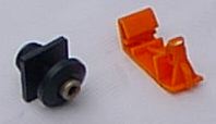
There are new rubber plugs that were used in the MGF production since about September 1997
The part No. is 14A7090A
4 pieces are required to shut the holes in the boot lid.
I've two pictures online on my MGF Parts list:
Fitting Location
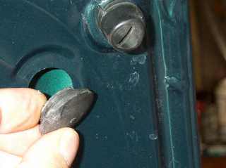
The way they look:
![]()
There are central jacking points both front and rear, the rear is the U-shaped thing hanging down at the rear.
Others use a trolley jack, suitably padded, under the longitudinal sub frame members for each wheel instead of the standard jacking points, it seems kinder. Some will probably use two jacks under both sub frame members to lift the entire front/rear, when it comes to that.

First remove the radio. Then there are four trim clips holding the panel in
place: one near the gear lever, at the rear of the panel; one either side of
the radio, just above the aperture; last one above the hazard switch.
Release the panel, and remove the block connectors from the rear of the
switches and clocks, and the whole assembly lift clear.
Whilst at this stage, I relocated a couple of switches: the front fogs switch
is now next to me- far more convenient, and the rear demist only gets used
occasionally in the winter. That switch is now located nearer the passenger. I
also swapped the oil temp and clock around so now the oil temp gauge is
closest to the driver.
Hoods - �200 +�10 delivery from Universal Salvage near Bedford
Fabric Seats - �200
Half Leather - �350
Tel. 01234 765555 (Wed afternoons is best time)
Type=Double Platinum Champion RC8 PYP / Unipart GSP 9652
Gap = 0.9mm 0.1 mm
Torque settings=25 Nm
Standard copper plugs use NGK BKR6E for single
earth electrode units that are best replaced at 6000 miles intervals for
maintenance of peak performance, keep standard gaps.
Alternative 2 or 4 earth electrode plugs are available such as NGK's BKR6EK
and then Bosche do the 4 earth electrode ones the part number of which I can't
remember. Sold in the UK under the 'Bosch Super4' title. The advantage of
multiple earth electrodes is that they last longer by evening out the erosion
of the electrodes, especially the centre one. Expect these to start going off
at about 10 to 12000 miles when replacement is advised to keep performance
crisp.
The standard MGF plugs are platinum for both electrodes which has a very, very
low wear rate. As such these last very much longer, and should do with the
difference in price! The only reason that the MGF has these and not a standard
type is down to the inaccessibility of the engine.
However the OE plugs are very good (Champion made) and have an official change
interval of 60,000 miles. I however feel that there will be a discernable
advantage in changing these at half that mileage. This advantage will be in
the way of a crisper throttle response and possibly slightly improved fuel
returns. Don't expect any power gains to write hope about, a dyno would be
needed to detect these.
The NGK application for all MGFs is PFR6N-11.
Don't bother with any of the fancy claims of various suppliers of non standard
ignition parts, as when working properly the standard system has more than
enough power to provide ALL of the ignition needs of the engines.
The grip that can be exerted by the plug sockets on the plugs is amazing. I often find on the 'older' K engined cars that I have to gently grip the ends with pliers and ease them off. What you have to be careful of is not to break the plastic ends which if you simply grab with pliers will happen. I find that long nosed pliers used to grip the two grooves either side of the top is a good way to introduce enough gentle leverage to pop them off.
Newton do a seat lowering kit for �10. It replaces some fixed bars
underneath the seat pads with springs so that they will give a bit more when you
sit on it.
The ultimate effect is to move your head a inch further from the roof - and for
a 6'2" customer it satisfies his objective.
The mark 2 MGF was launched at the end of 1999. The new model features:
At the rear, jack up the car and remove one of the wheels. Stick a short piece of masking tape on the front edge of the bumper approximately where the top hole of the mudflap will be. Remove the screw holding the splashguard to the front edge of the bumper and fit the mudflap temporarily using one of the supplied long screws. Now mark the position of the top hole through the mudflap on the masking tape. Remove the mudflap and follow the fitting instructions. It is quite easy to drill the hole in the bumper through the masking tape holding the drill bit in the hand, turning the bit a quarter turn and back until the hole is formed: it may cause less damage than a power tool.
It is possible to remove a wheel without excessive force, although it does require time and effort depending on the extent of the corrosive bond, and is best done before an emergency strikes. Jack up the wheel securely, and slacken the wheelnuts so that they have half a turn clearance. Grasp the top of the tyre with both hands and pull sharply outwards. Turn the wheel 90 degrees and pull again. Continue turning and pulling until the wheel comes up against the wheelnuts. Slacken the wheelnuts another half a turn and continue pulling. The wheelnuts will ensure that the wheel is coming off squarely, which is essential. Eventually the wheel will be free.
However the wheel is removed it should always be pulled off the hub squarely for the first half-inch or so to avoid damage to the spigot or recess, and replaced similarly with the wheelnut spindles as central as possible in the wheelnut holes. Many wheel removal problems are caused by jamming the wheel on the spigot. When the wheel is off clean the spigot and wheel recess and smear a generous amount of copper grease or other corrosive protectant on both. Apply a little copper grease to the wheelnut studs before replacing the wheel and tightening the nuts. This routine, now with very little effort, should be repeated yearly.
The Bosch ABS system works irrespective of
vehicle weight. Each wheel speed is measured via the toothed sensor attached
as part of the rotating hub assembly. Very simply the ABS functions as a three
stage device.
1, is the normal transmission of fluid pressure from the brake pedal direct to
the wheel cylinders.
2, is when the system 'reads' the wheel speeds to have a variation of more
than 20%. Usually this is when one wheel is turning slower than the others and
indicates that this wheel is on the final stages prior to locking. When this
is detected the ABS valving isolates the fluid line to that affected wheel.
Pressure in the line is maintained, but additional pedal presssure results in
no more pressure being applied to that wheel.
3, if the wheel speed doesn't stabilise then the system will then 'bleed' some
of the fluid pressure from that line. This will reduce the braking effect on
that wheel with the intention that it's rotational speed will stabilise with
the others. If the wheel speed doesn't increase, for example when on ice, more
fluid is 'bled' from that line until it does stabilise.
This all happens in a very very short period of time and once the wheel speeds
stabilise and if the brake pedal is still being applied then fluid pressure
will be allowed to pass once again to the wheel cylinders. If the wheel speeds
then venture outside that 20% threshold then the above is repeated again.
The speed of each cycle is so fast that a number of cycles will have occurred
before you can reduce pedal pressure. This will mean that during each cycle an
amount of fluid will have been 'bled' from the line between the ABS valve
block (The under bonnet unit) and wheel(s) affected.
If nothing is done then you will suddenly find your foot on the floor with no
pedal, so to ensure that you retain a pedal and control the ABS pump comes
into operation and forces the returned fluid back into the system between the
master cylinder and the ABS unit. This requires very high pressures and is why
the pump draws so much electrical power. The pulsing (buzzing) is the
operation of the pump and is felt in through the pedal.
The operation of the system will occur on any surface from ice to the
grippiest surface available. The only proviso being the variation of
individual wheel speeds.
The ABS system always defaults to normal braking if any fault is detected.
The most common fault by far is a failure of one of the wheel sensors. Which
one can be located quite easily with a sensitive voltmeter. Find the loom
connections where the wheel sensor lead plugs into the main loom and unplug
each sensor. Connect the two probes to the sensor terminal.
Jack that wheel off the ground and spin it over by hand. You should get a
small pulsating current generation corresponding to each toothed segment of
the wheel sensor. If the pulse is present move to the next wheel. You will
find one that doesn't give any reading and that will be the one that has
failed.
Problem is that replacement sensors are not cheap, are delicate and easily
damaged, and as such are often difficult to remove from a crashed car if you
want a second hand one. I have come across many ABS equipped cars where sensor
replacement has been a low priority of the owner and a bulb removal in the
dash is the preferred option. Check your bulb hasn't been removed if the car
was bought second hand!!
Greg Hilton drop me an email if you wish to add something useful to these pages.
NOTE: Remove the words NOSPAM from the above address to mail me.
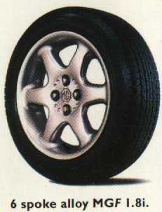
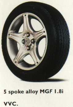
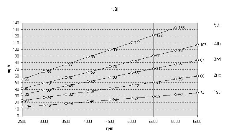
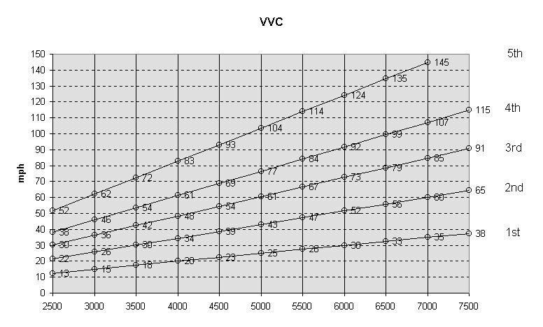
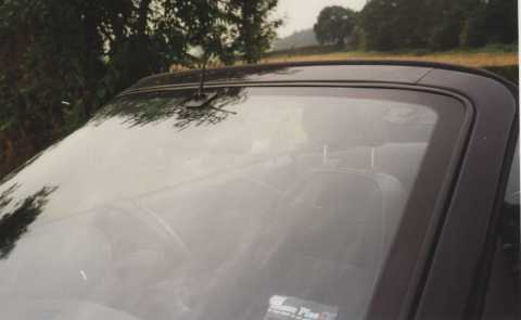
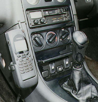
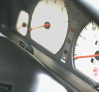
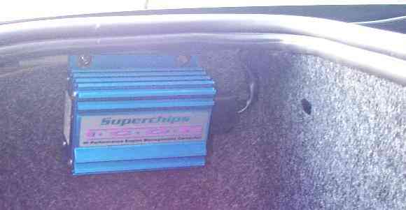
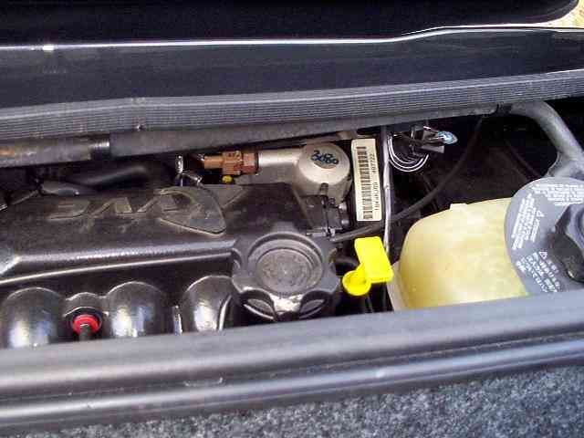
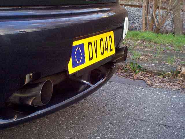
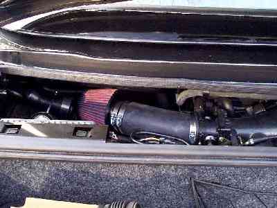
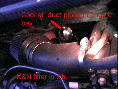
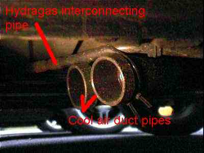
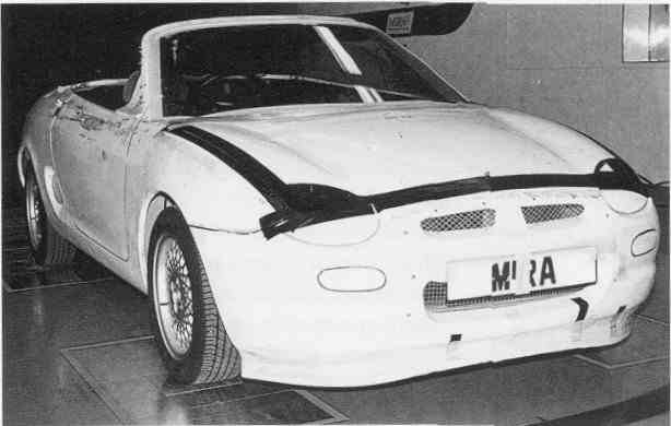
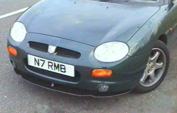