Technical Articles (during lockdown)
Installing relays
into older classic cars
Why do enthusiasts fit
relays in their cars?
Well possibly for a couple of reasons, but the most benefit would be derived from modifying the headlight circuit. The benefits hopefully when relays are fitted to this circuit will be that the headlights will be substantially brighter. Could that be true? Well with a little testing the answer ought to be evident, after which we can look at how to fit the relays if required.
Besides benefits to the
lighting circuit of brighter lights there is another benefit to fitting relays
in other circuits. When switches are operated, especially in higher powered DC
circuits, a flash can occur across the contacts of the switch. After a time this
flashing (normally referred to as arcing) will cause severe burning to the
switch contacts, causing poor operation and finally a complete failure of the
switch. When relays are fitted into a circuit the power through the switch is
drastically reduced and so arcing is suppressed and the switch will last far
longer. This of course is beneficial to the headlamp switch, the dipswitch in
the lighting circuit and also other switches such as the brake light switch all
of which can be protected with the use of relays.
How does fitting relays protect switches? Well if the
switch on the dashboard is only required to switch the load of the relay instead
of the load created by the headlamps then the current flowing through the switch
will be greatly reduced and the switch ought to be far more reliable. Let me
point out at this point I am pretty sure that the vast majority of the dashboard
switches on our cars are more than adequate for the job they do but I am simply
describing the suggested benefits of relays. It can be pointed out that in
modern cars most circuits are operated via relays so they must be better? Well
of course that is true however in modern cars the relays perform other
functions. They actually perform functions that we refer to as logic such as a
number of different ways to operate a circuit over and above a simple switch. On
top of this you will notice that modern dashboard switches are far smaller than
the large toggle switches we find in older cars, the use of these smaller
lighter switches is only made possible by the use of numerous relays.
OK so that seems
straightforward enough but if the headlights glow brighter with increased
voltage, then they will also glow significantly dimmer were the voltage to
reduce. What then could be the reasons why this voltage maybe reduced? If the
light bulb was connected directly across the battery then it would be as bright
as possible. However the light bulb is not connected directly across the battery
but is actually installed at the front of the car. It is then connected to the
battery by a circuit that contains a lighting switch, a dip switch and numerous
connections (bullets). Each one of these switches and connections could reduce
the voltage applied to the headlight bulbs due to poor connections leading to
high resistance and reduced voltage.
Whilst my car is well modified in plenty of other areas I
still make use of the original dip switch on the column and part of the original
harness from just under the scuttle to the front of the car where there is all
the original bullet connectors connecting wires to both headlamps. I decided to
do some testing to assess any problems with my headlamp circuits and began by
switching on the headlights, I then measured the voltage from the battery
positive to the negative (body) (This demonstrates how much voltage is
available). I then measured the voltage at a point in the front of the car where
the original bullet connector splits the feed to both headlamps, if everything
was working fine this ought to be the same value as the battery. However I was
staggered the difference was more than 1 volt and was nearer 1.5 volts (that is
more than a 10% reduction). I used a prong on my meter to poke into the bullet
to make a connection to the meter as it is absolutely essential to have the
lights switched on and operating to do this test. If the lights were to be
disconnected to do the test and the measurement made then there would be
absolutely no difference between the 2 readings and the test would be a waste of
time. After doing the voltage reduction test I decided to do another test to be
sure the readings were accurate. This time I connected a piece of wire to the
battery positive, the other end of the wire I connected into the bullet where I
had previously measured the reduced voltage. As I pushed it in and out of the
bullet a very noticeable increase and decrease in brilliance of the headlight
was easy to see, proving that voltage had reduced in the original circuit
causing a dimmer performance of the headlights.
So where was the point of high resistance that was
potentially causing my dim headlamps? Well to determine where the voltage is
being lost sounds an easy task but is quite difficult in practice. What we need
to do is to do the test described above at all connection points within the
circuit remembering that the lights have to be switched on whilst doing the
test. That means we need to access various switches and connections, many hidden
behind the dashboard or tucked into the steering column. I managed to do most of
them and I found out where my headlamp circuit was losing voltage and it was in
one place only. The voltage was disappearing across the “dipswitch” which of
course is located as a switch on the steering column. Those of you who are
familiar with these switches will of course not be surprised by this loss and
would probably have guessed that it would indeed be the problem area. I suppose
I could have purchased a new switch but considering popular opinion on the
quality of these items it is far easier and far cheaper to regain maximum
headlamp brilliance by simply fitting relays.
What is a Relay
The relay consists of 2 circuits and therefore generally
has 4 connections. The first circuit is known as the coil and it is the circuit
that will be operated by the original switch. Within the relay this coil when
energised (powered) becomes magnetic and attracts a metal former towards the
core. This is connected to a contact in circuit 2 and therefore when this occurs
the 2 connections on circuit 2 join together and will operate/power/switch
whatever is connected to them and thus replicate the action of the original
switch.
With reference to the photo of a relay it can be noted
that 4 connections can be seen on the base. On inspection it can also be noted
that most relays will have each of these connection numbered, these numbers are
almost always the same and so will dictate how the relay should be connected.
However what is not the same on all relays is the physical arrangement of the
connections and so reference to the connection numbers is always necessary to
ensure correct connection and operation. The numbering system is easy with the
coil being on connections 85 and 86, whilst the contact is on connections 30 and
87. A very cheap supply for these relays is for you to take a trip to a scrap
yard and you will find under the bonnet of all modern cars a fuse box that will
contain a number of relays. These can be pulled out of the base of the fuse box
and can be used for our modifications.
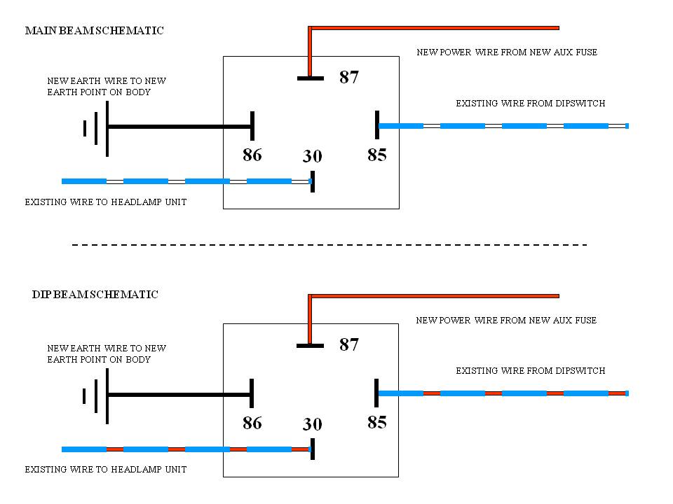
Fitting relays
To change the lighting circuit to relay operation
requires 2 relays, one for the main beam circuit and the other for the dip beam
circuit. First let’s concentrate on the main beam circuit. In both modified
circuits we use the original wiring to operate the coil of the relay this on pin
85 with pin 86 now connected to earth. The original main beam wiring is coloured
Blue with white tracer from the dip switch to the main beam headlight. This has
to be connected to pin 85 on the relay so it either needs cutting at some point
to make the connection or perhaps disconnected from the headlight and routed
back. On my car I mounted the relays on my inner wing about halfway between the
switch and the actual headlight. I stripped back the loom insulation and found
the blue wire with the white tracer. Cutting the wire here I then needed to
extend each cut end to make it long enough to connect to the relay on the inner
wing. Looking in my spares/rubbish draws I found some blue wire with white
tracer that I could use to make the connections, so for me I simply connected
the extra wire to the relay terminals with soldered female spades and these
wires were then soldered onto the cut wire in the existing loom. To insulate
these new soldered connections I used heat shrink that makes a reasonably neat
job and then re wrap the loom with a few turns of tape. So the connections on
the new relay need to be connected these need the blue wire with the white
tracer connected to pin 85, pin 86 to a new wire connected to the body earth, a
new power wire to be connected to pin 87. This I ran from an always live
connection on my fuse box alternatively this could be connected to the battery
and an inline fuse used for protection. Then finally a connection from pin 30
requires connection to the original Blue wire with white tracer that connected
to the headlight unit.
So to recap the existing blue/white wire was cut in the
loom and a new piece was soldered to it and connected to pin 85 on the relay
base with a soldered female spade. From pin 30 another new piece of wiring is
then soldered onto the other cut piece of wire in the loom that is connected to
the headlight. To finish the wiring
installation a new live wire is connected to a new always live fuse and
connected to pin 87 and finally the new earth wire is connected to pin 86 and
the car body earth.
This effectively completes the
wiring for the Main beam and now the dip beam can be modified. This is very
similar to the modification of the main beam circuit except instead of working
on the blue with white tracer wiring simply substitute blue with red tracer. The
new power wire that was installed from a new always live fuse can be split near
the 2 relays and used to power both circuits. The source of this new supply
should be from an always live fuse in the fuse box or better still connect a new
wire to the battery cable (probably best fitted at the starter solenoid) then
through a new inline fuse before connecting to the relays.
The connections I make with the
spade connections on the relay I always do with a soldered connection. I find
the mechanically crimped connections very poor and to make these a quality
soldered joint is very easy. Instead of crimping these simply solder the wire
into the crimp and then I use a short piece of shrink wrap to insulate the spade
terminal.
This work I did on my Midget,
however fitting relays is very similar on all of our models. The colours on the
Midget are typical Lucas colours and are the same as many vehicles of the era.
However what ever vehicle you intend to modify it is important to make sure of
the relevant colours of the wiring before commencing the task.
Finally this technique can be
used to modify any such circuit in the very same manner as the headlights. As an
example if you wanted to protect the brake light switch with a relay then simply
find the green wire with a purple tracer and modify it exactly as you have done
to the headlight circuit.
Replacing the metal
coolant pipes on an MGTF –
Robert Taylor
The MGF and MGTF are renowned
for overheating issues and one of the reasons is that the volume of coolant is
small especially as it has to be piped from the rear engine to the front mounted
radiator and back again. A key part of this process is the approx. 2m long metal
coolant pipes that run under the car. These pipes are prone to rusting
and, as stainless steel replacements are
readily available, I decided to tackle the replacement. It is easy to get an air
lock in the coolant system so before tackling the work ensure that you are aware
of the correct bleeding procedure as explained later.
I first of all raised the car front and back using ramps
and axle stands. Set the heater controls to maximum so as to drain all or most
of the coolant which will later be replaced with fresh coolant. Remove the
expansion tank filler cap. There is no drain plug so release one of the hose
clips on the metal coolant pipe and allow the coolant to drain into a container.
There is a thick underfloor strengthening plate secured with approx. 24 bolts (see photo1).
.jpg) Photo 1 |
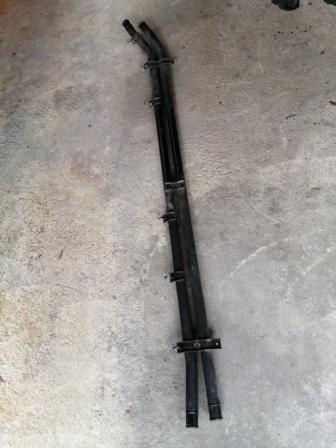 Photo 2 |
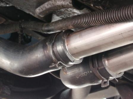 Photo 3 |
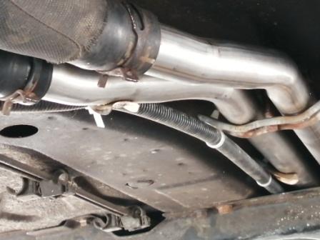 Photo 4 |
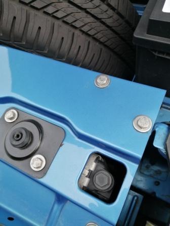 Photo 5 |
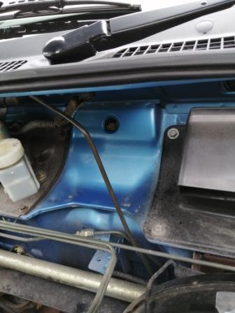 Photo 6 |
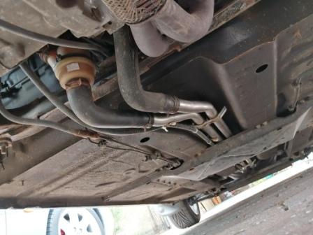 Photo 7 |
||
This needs to be removed to gain access to the metal
coolant pipes. Next, cut the cable ties that secure the main feed cable from the
battery that runs the length of the underside. Having allowed the coolant to
drain the other hose clips can be released and moved back on the rubber hoses. I
purchased replacement jubilee type hose clips in case they were needed but in
fact the original spring type hose clips were serviceable and retained for
originality. It is now possible to undo the 3 retaining bolts and remove the
metal coolant pipes (see photo2). The cooling system can now be flushed with
clear water and the radiator reverse flushed.
New cable ties were supplied
with the stainless steel coolant pipes but check before fitting that when the
main feed cable from the battery is cable tied in place there are no sharp edges
likely to cut into the cable. I filed down some sharp edges before fitting. The
new coolant pipe can be bolted into place, the rubber hoses fitted and secured
with the hose clips and the underfloor strengthening plate refitted. Ensure all
the bolts are replaced and correctly tightened as this is a structural item
evidenced by the number of bolts used.
See Photos 3 and 4 showing the front and rear
connections to the rubber hoses. It goes without saying that the rubber hoses
should be checked for condition and replaced if necessary at the same time.
However, the hoses on my 2005 TF were in good pliable condition with no sign of
cracking.
The recommended antifreeze is ethylene glycol based
containing OAT corrosion inhibitors which is pink in colour. The amount required
is 5.25 litres and a concentration of 50% is required to ensure the
anti-corrosion properties are maintained and not above 60% as cooling
efficiencies will be impaired.
It is important to follow the correct re-filling and
bleeding procedure otherwise an air lock could occur resulting to overheating.
1.
Turn the heater control to
max heat.
2.
Remove the bleed screw from
the top of the radiator (see photo 5)
3.
Open the heater bleed screw
(see photo 6) found behind the black plastic cover at the
rear of the front storage compartment.
4.
Fill the system from the
expansion tank taking care to keep the expansion tank full to prevent air
entering the system.
5.
When a constant flow of
coolant is being emitted from both bleed points close the radiator bleed screw
and then the heater bleed screw.
6.
Ensure the expansion tank is
topped up, fit the cap and run the engine until the engine reaches full
operating temperature. (Note: Do not operate the air conditioning if fitted.)
7.
Check the cooling system for
leaks and that the heater is emitting heat. If the heater is not emitting heat
there may be an air lock and the “Additional bleed” procedure should be
undertaken.
8.
This involves removing the engine compartment access panel, releasing the clip
and removing the inlet air hose from the throttle housing. This gives access to
the additional bleed screw on the radiator return valve.
I suggest taking the car for a short test run to ensure
the cooling system is working correctly before embarking on a journey.
Whilst I had the black plastic cover removed in the
front storage compartment I took the opportunity to remove the screen washer
bottle and give it a thorough clean out to prevent future blockages of the
screen washer jets. A minor maintenance task that saves much frustration if
overlooked.