
 Click here to add your MG News.
Click here to add your MG News.
Like many MMM owners, I had a well worn brake cross-shaft assembly with the handbrake waving in the breeze and the ratchet support bearing rattling on the shaft. This article tells the story of my progress in restoring this typically aged shaft, from my MG PA, through the various ideas and stages of rebuilding to an assembly with a new shaft, new foot brake lever and updated bearings. Additionally a second assembly, from a J2, was rebuilt to standard specification. The whole operation has taken several years of occasional work interrupted by such trivial events as moving house.
The MMM brake cross shaft assembly seems to be a neglected item, perhaps because, with everything welded in place, it only gets reconditioned, or simply replaced, when it really is totally unusable. Maybe, because of this, there appears to have been little written about its rebuilding.
The P-Type assembly is identical to that of J-types and presumably similar to the other MMM cars with, I believe, the exception of M-types.
Plan "A" Minimum Work
My first thoughts were to clean everything and to simply (?) replace the bronze bearing bush at the nearside end and bushes in the handbrake and ratchet support plate. For the latter two, I intended to drive the old bushes out of their housings, cutting them off the shaft and replacing them with split bushes. This approach was designed to avoid removing any of the items that were welded to the shaft. The split bush appraoch was one I had used as an apprentice in the pump industry and although there were plenty of likely problems, I thought I could make it work.
This idea had to be abandoned very quickly because of the impossibility of removing the bush from the handbrake. This bush has a thin wall, which had bell-mouthed away to nearly nothing at both ends and was almost impossible to see let alone press out, even if I had made an elaborate tool to do so.
The second problem of uneven wear on the shelf was revealed when the collar was freed and the handbrake lever was moved along the shaft. Even a new bush would not have taken up this wear sufficiently to prevent the handbrake waving around.
Plan "B" More Work
So to Plan "B" - file through the welds of one pulley and the handbrake arm on the shaft. This would allow the handbrake lever and steady bearing to be removed and re-bushed and the shaft to be metal sprayed and machined back to its original size.
At this stage the footbrake lever seemed acceptable and not to have too much clearance on the shaft.
Before removing anything, sketches were made of the shaft and levers with particular attention to their angular position. I reasoned that if I had to make such an assembly, I would load all the parts into a jig, clamp them and weld them, however, I was wrong, as I discovered later and need not have made such a detailed sketch.
Filing the welds away requires infinite patience, which I don't possess, so I resorted to an angle grinder. This enabled the welds to be cut in reasonable time but did not improve the state of the shaft in the lathe and turned through the welds but I was afraid that the handbrake could seize on the shaft and I would be left with a bent, irreplaceable handbrake lever.
Subsequent enquiries revealed that metal spraying required a 0.015" (0.4mm) deep groove to be cut into the 0.128" (3.25mm) wall of this tubular shaft. This weakening of the body of the shaft, the cost of spraying and remachining and the additional damage to the shaft caused by my impatience, ruled out metal spraying, so Plan "B" was abandoned.
Plan "C" - The Ultimate Rebuild
Finally, of necessity, Plan "C" emerged. In addition to re-bushing the handbrake and support bearing, a new cross shaft would have to be acquired, the remaining levers and pulley would have to be removed from the old shaft and the whole lot reassembled and welded onto a new shaft.
I need not have bothered with the angular details on my sketches because all the pulleys and levers were keyed in position with very shallow rectangular and woodruff keys respectively.
Sourcing a Shaft and "Good" Advice
Enquiries of our main spares suppliers revealed that none kept new bare brake cross shafts nor knew of a source. The best I could get was the suggestion that all I needed to do was to "Cut the shaft in half. Get a couple of bushes knocked up for a 'tenner' at a local machine shop, fit them and weld the shaft ends together."
I was personally horrified by this advice. As the brake cross shaft is the heart of the braking system, its failure could lead to fatal results and a weld can often have less strength than the parent metal. It seemed to me to be asking for trouble. Of course cutting, sleeving and welding would allow the handbrake lever and ratchet mounting plate bushes to be replaced, but only cutting through the welds and removing one arm, after cutting the shaft in half, will access to the footbrake lever.
At this stage it seemed that the only route was to make or have a new shaft
made. I made a drawing of the cross shaft and brought some suitable
material -
1.125" o/d x 8 swg wall thickness (0.16", 4mm) Cold Drawn Seamless (CDS2)
steel tube to BS1734. I used tube with a thicker wall then the original,
partly because calculations showed that the woodruff keyways could break
through the original thickness of wall, but mainly to use what was readily
available in a suitable quantity. I brought enough tube for 2 shafts in case
I ruined one and because that was the quantity available for the minimum
order charge!
A Slight Diversion
I had planned to make enquiries of the local machine shops to get a new shaft made from my material and to my drawing. However, my interest in making things, the availability of a lathe and items to make a suitable attachment for light milling to be done on it, and a period of unemployment all directed me to make my own.
Almost as an aside, I had to build up a vertical slide attachment to enable my lathe to be used as a milling machine to cut the keyways in the shaft and construct a suitable method of getting them at the correct angles to each other. Although very basic, the arrangement worked well enough to successfully produce two shafts.
Another One to Rebuild
At about this time, John James remembered my advert for a bare brake
cross-shaft in the Bulletin and enquired whether I still had it. This
enquiry resulted in his agreeing to let me rebuild his cross-shaft assembly
and standing in my garage one Sunday afternoon watching me cut his old
cross-shaft in half and machine away the welds from the various levers. This
was a much easier and cleaner method of removing these bits than my first
effort!
So two shafts were rebuilt in parallel, although John's had a complete,
serviceable original roller bearing on the offside, so needed only a bronze
bush for the near-side.
Bearings
One consideration for my own shaft was the bearings. Both the original bearings were unserviceable. The bronze bush had worn and the needle roller bearing had rollers missing. My first thought was to use the 2 bronze bushes. However, a conversation at a "natter" well lubricated with beer, turned to the possibility of fitting needle roller bearings throughout the MMM braking system and with this in mind, I decided to use needle rollers at both ends of my cross-shaft.
Graham Howell told me that the original needle rollers were 2mm diameter and
no longer available, so I had find an alternative. With the aid of an old
Torrington bearing catalogue, I found a suitable bearing and inner sleeve
only to discover that both were obsolete. However there were 50 bearings
left in stock at BSL in Birmingham but no sleeves to fit the standard shaft
retaining bolts and provide 17mm diameter for the bearings. These were
necessary because there is no possibility of increasing the diameter of the
"pin" of the bolts to 17mm without increasing the size of the 11/16" BSF
thread in the chassis mounting flange.
I also had to fractionally adjust the bore dimensions in the ends of my
cross-shaft to accommodate the metric outside diameter of the new bearings.
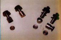
| The advantage I saw of using assembled needle roller bearings rather than the original loose rollers was that a hardened outer tack would be present instead of the relatively soft steel of the shaft. (My adapter sleeves were made from a hardenable steel and hardened). Photo 1 shows the two types of bearings - standard on the left. |
|
A Further Problem
A further problem I encountered was the worn state of the lever which connects to the footbrake. Although it seemed serviceable when on the shaft, after removal, and cleaning off years of hardened dirt and lubricant, it was a slack fit. Again, first thoughts were to salvage the existing part by boring out and bushing, but this was not an option because the wall thickness was too thin. Building up the bore with weld and re-machining it to size was tried but abandoned because of the difficulty in gripping and aligning the part in the lathe (to re-machine the bore) and my having second thoughts about its strength.
Finally I acquired a piece of steel strip and proceeded to machine a new lever 4" x3/4" (100 x 19mm) would have been the best size, but 4" x 1" (100 x 25mm) was readily available.
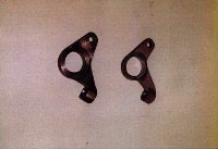
| Photo 2 well illustrates the thin section of the original lever on the left with the thicker new one on the right. |
|
Meanwhile, I had the handbrake lever re-plated, I can only hope that with suitable care the plating will last until the cross-shaft assembly has to be dismantled again for reconditioning.
Getting it Together
For both sets of parts, the new bronze bushes were pressed into the brake lever and ratchet mounting plate. The bush in the brake lever was reamed to size (it's a reasonable length) but the ratchet mounting was put in the 4-jaw chuck in the lathe and bored to size. I didn't trust myself to get a 1 1/8 inch reamer square through such as short bush!
All was now ready for cleaning and because the facility was available, I grit-blasted all the pulleys and arms.
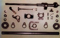
| I now, finally, had two complete sets of parts awaiting building into brake cross-shaft assemblies. A single set of parts is shown in Photo 3. |
|
The keys were fitted to the cross-shaft, making sure that the mating lever or pulley slid over its respective key but was a close fit on the shaft. All the levers (fortunately) had to be eased to fit the new shaft. Before welding, a plug was made for the shaft ends to prevent distortion of the bearing bores during the fitting of the pulleys.
The footbrake levers were put on the shaft first and welded in position, after checking the orientation of the arms and lever against the illustration in the handbook several times and ensuring that the lever was free to turn.
The collar, ratchet support plate, handbrake lever and arm followed and the arm was welded in place. Care and checking were needed when fitting the ratchet mounting plate which is asymmetrical and can easily be fitted incorrectly. (I did it, but corrected it before welding the arm in place!)
Next the shaft ends were plugged and the pulleys with keys were fitted over and welded to the shaft end. Care was taken to weld on alternate sides of the pulleys to correct any tipping.
Re-positioning the various arms was remarkably easy; they simply fitted over and were centralised on their respective keys. The pulleys had to be set the correct distance from the shaft ends and this is where the sketch did have to be used.
MIG welding was used for convenience rather than the original arc welding. The only problem foreseen with this is the next reconditioning in 40 or so years when the harder MIG weld metal will be more difficult to get off!
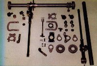
| With all the arms welded in place, the handbrake retaining collar was set in position with a screw which was pilot-drilled. A drill was then put down the centre of this screw to cut a pilot hole in the cross-shaft, which was opened up to the required size. The reason for using this method was to achieve the best location of the collar and to minimise sideways movement of the handbrake lever. Photo 4 shows one assembly with the standard bearings to be fitted and the kit or parts for the second assembly with the roller bearings. |
 |
After a final clean of the shaft bore, de-burring of the hole for the collar screw and other general cleaning, the bearings were fitted.
Lubrication
The standard needle roller bearing has a blank plate at its inner end. This
means that the off-side lubrication pipe only feeds the needle roller
bearing. The bronze bush fitted to the near-side is drilled through to allow
oil into the hollow shaft to provide lubrication to the hand and footbrake
levers.
The shaft must thus be kept half-full of oil, all of which is supplied
through the 1/8 inch (3.2mm) hole in the bearing bush.
On my own shaft with 2 needle roller bearings, the backplates to the bearings
are drilled off-centre to allow oil in from both ends and to maintain the
shaft 3/4 full to try to ensure better lubrication of the hand and footbrake
levers.
Lubrication of the hand and footbrake lever bearing surfaces seems to take place every time the shaft rotates and the oil holes in the side go below the oil level inside the shaft, hence the need to keep the shaft topped up with oil.
There is of course no sealing at the open end of the cross-shaft bearings so one would expect some oil to leak out. Although this does not appear to affect the life of the cross-shaft, sealing would seem to be beneficial, if only to help to keep road dirt out and the garage floor clean. I have not yet thought seriously about it, but with the very limited space between the ends of the shaft and the chassis rails, very soft O rings or felt washers could be the answer.
Conclusion
This task has shown that there really are no short-cuts. Experience with my own and John James' cross-shafts makes me suspect that many are in the same well-worn state.
I hope that this article demonstrates that it is perfectly possible to rebuild a MMM brake cross-shaft assembly with a lot of determination and access to fairly basic machinery.
John James has now installed his rebuilt cross-shaft successfully in his rolling chassis and I have checked that mine will fit, but as my own car is nowhere near being assembled, my cross-shaft is being stored away to await the rolling chassis to go with it!
Geoff Taylor
Back to the News content
![[Copyright/Credits]](../pics/mini-copyright.gif)
![[Home]](../pics/mini-home.gif)
![[Information]](../pics/mini-info.gif)
![[Feedback]](../pics/mini-mail.gif)