These pages contain detailed information about the wiring looms used in the MGTD and MGTF. The first section, from Barrie Jones, contains information about the wiring color codes used inside the harnesses. The second section, from Bruce Sharman of Bygone Spares and Restorations, describes the loom outer coverings or sheath in great detail. The last section deals with battery cables with information provided by Rob Grantham, Australia.
The automotive wiring colour code that we know today was invented around
1936. I believe the company that invented and maintained it was Ripaults, not
Lucas. Ripaults Cables Ltd is a long-established manufacturer of automotive
cable and wiring looms in the UK.
The Ripaults colour code quickly
became the de facto standard in the UK. Each colour was denoted by a unique
letter, and some letters were reserved for other purposes. MG did follow the
colour code, but unfortunately they did not use the letters on their wiring
diagrams until 1962, staying with an earlier system where the wiring diagram
used numbers and a cross-reference table was required.
Different codes
were followed in other countries, and many cars sold in the UK used the German
code, particularly VW. Ford cars could have either UK or German looms,
depending on where they were built.
Reserved letters
A = Ammeter
D = Dynamo
E = Earth
F = Field coils
L = Light or Lights (as in head light, and also light green!)
Colours
B = Black
R = Red
O = Orange
W = White
N = browN
U = blUe
G = Green
P = Purple
Y = Yellow
The only significant change to the colour code was around 1955, when the
primary colour Yellow was changed to Brown. Secondary colours were not changed
at that time, so Yellow with a Red stripe became Brown with a Red stripe, etc.
The special cases were:
Plain Yellow became Brown with a Yellow stripe, and
Yellow with a Brown stripe became plain Brown.
MG continued to use Yellow on the TF and all the MGAs, only changing to
Brown when they introduced the MGB in 1962.
At some time, the primary colour of Purple was introduced for those
wires that were fused (A1-A2) and permanently live (e.g. the horn circuit). The
timing of this change is unclear, because some TDs used the new colour code,
although the TF and the MGA did not.
Since then, new colours have been added to the system, notably Light
Green (LG), Slate grey (S), Pink (K) and Orange (O). There is one light green
wire in the TF loom. I assume that Ripaults chose S for Slate grey because they
had already used G, R, E and Y.
The first table (following) shows the meaning of the primary colour. For
example, all white wires are part of the ignition circuit, they are not fused,
and they are switched via the ignition switch
Primary Colour Code
Primary Colour
Code
Use
Fused
Switched
White
W
A3 - Ignition & Fuel pump
no
Ignition
Black
B
Earth
no
no
Brown
N
Charging circuit
no
no
Yellow
Y
Charging circuit
no
no
Blue
U
Headlights
no
Headlight switch
Red
R
Sidelights
no
Sidelight switch
Green
G
A4 - brake lights, wiper motor &
heater
A3-A4
Ignition
Purple
P
A2 - horns & courtesy
lights
A1-A2
no
* some brown wires are fused prior to the introduction of
purple
The second table (following) shows most of the wires in the TF loom,
including those with a stripe. For example, the wire between the distributor
and the coil should be white with a black stripe, coded WB.
Full Colour Code (TF)
Primary Colour
Colour Code
Lucas Lettering
Use
Black
B
E
Earth
Brown
N
Battery to ammeter
Battery to fuse box A1
NU
A1
Light switch to regulator A1
NW
A
Ammeter to regulator A
NG
A2
Fuse box A2 to horns
NB
Horns to horn button
Yellow
Y
D
Dynamo D to regulator D Ignition
warning light to regulator D
YG
F
Dynamo F to regulator F
Blue
B
S2
Light switch to dip switch
BW
Dip switch to headlamp main
beam
Dip switch to headlamp warning
light
BR
Dip switch to headlamp dipped
beam
Red
R
S1
Light switch to sidelights
Light switch to number plate
light
Light switch to panel light
switch
Light switch to fog light
switch
RW
Panel light switch to panel
lights
White
W
A3
Ignition switch to coil SW
Ignition switch to fuse box A3
Ignition switch to ignition warning
light
WP *
Rear Nearside turn indicator &
brake light
WN *
Rear Offside turn indicator &
brake light
WB
CB
Coil to distributor contact
breaker
Green
G
A4
Fuse box A4 to turn indicator
switch
Fuse box A4 to turn indicator
relay
Fuse box A4 to wiper motor
switch
Fuse box A4 to petrol warning
light
Fuse box A4 to accessories (e g
heater)
Fuse box A4 to brake light
switch
GP
Brake light switch to turn indicator
relay
GB
Petrol tank sender to petrol warning
light
GR
Front Nearside turn indicator
GW
Front Offside turn indicator
* I know they are white, but logically they should have been
green
Full Colour Code (TC and TD)
Primary Colour
Colour Code
Lucas Lettering
Use
Black
B
E
Earth
Brown
N
Battery to ammeter
A1
Battery to separate fuse box
A1
NU
A1
Light switch to regulator A1
NW
A
Ammeter to regulator A
NG *
A2
Fuse box A2 to horns
NB *
Horns to horn button
Yellow
Y
D
Dynamo D to regulator
D Ignition warning light to regulator D
YG
F
Dynamo F to regulator F
Blue
B
S2
Light switch to dip switch
BW
Dip switch to headlamp main
beam Dip switch to headlamp warning light
I
have original samples of wiring harnesses in my “museum” for want of a
better description. It appears from our samples and research that Vic
Longden carried out that most Lucas harnesses started out black. As an
electrical change was made in the circuitry, then a coloured trace was
added to the outer braid. When another change occurred another trace was
added. We believe that this aided the car manufacturer (for example MG)
identify the harnesses and ensure they were fitted correctly to the
correct model. This was not necessarily at “official” model change, but
could occur midway through a production run or could be for changes in
the circuitry for export models.
I have most of the colours from M types through to the last of the MGBs. This can be
quite complicated as some of the cars with several components to the
harness, could have different colours in each part of the harness,
depending if a change occurred to that particular section. Also as
already mentioned the colours change midway through a production run of a
particular model, so a lot of my information also relates back to
a chassis number rather than model type. Then to add to this complication
during the fifties some cars had a combination of Khaki and black. Our
theory is this may have been due to cotton or dye shortages post war. Then throw into this mix the fact that the earlier cars (up to late 40s ish) are braided
with 4 strand thick cotton as opposed to the later cars which have 6 strand cotton braiding.
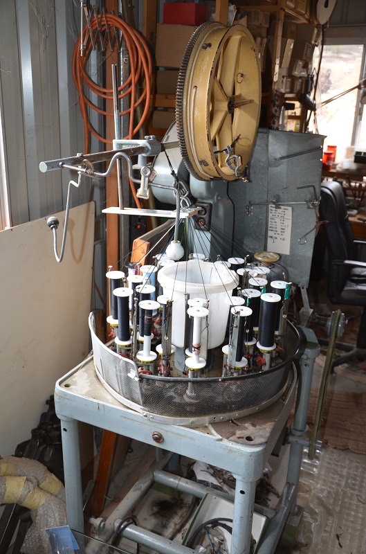
A few words about the direction of the tracer and braiding
It is all based on the braiding machine. This machine has 24 bobbins. 12 with cotton running to the RH side of the braid
and 12 running to the LH side of the braid. It works like a maypole, with the bobbins going around and under over each other,
just like dancers round a maypole. If I am using this / symbol it means the trace is running to the RH side of the braid,
( so looking from above this dancer is running clockwise (CW), when using this \ the trace is running to the LH side of
braid and the dancer would be running anti clockwise (ACW). When using this X symbol there is one dancer running CW and one
running ACW When using this //\ symbol there are 2 dancer next to each other running CW and one running ACW When
using / black / black /. There are 3 dancers running CW with a black dancer in between each.
The norm then is to run the braid from each sub branch end to the main branch (using a tree as an analogy).
Once this is completed then run the braid down each main branch to the trunk. Once all are completed then we start at the
thickest end (usually dash end) and braid down the main trunk. Sorry if this is confusing, but it is the only way I can explain
the direction the trace runs down the harness without seeing the machine in operation. Again distance between traces varies
because of the machine. If there are only a few wires, distance is generally about ¾". Where there is a big thick
bunch of wires, i.e. bulkhead area it can increase to about 1" spacing.
Short video of Bruce's braiding machine in action.
MGTD Harnesses
The following tables describes the harness during the production of the MGTD.
On the MGTD harness all are six strand, both body and tracers. All TD harnesses were black. At one time it was thought that some TD's had brown looms but it is now believed the dies were variable and the brown harnesses were just faded black harnesses.
Car Number Range
Harness Type
Drive
Tracer Colour
Direction
Comment
0251 - 8141 with RF95 regulator
Main
Right
Yellow
/
8142 - 19299 with RB106 regulator
Main
Right
Yellow
/
At one time thought to be a white tracer but now believed to be yellow
9300 to end
Main
Right
Yellow
/
0251 - 8141 with RF95 regulator
Main
Left
Yellow
X
Crossed yellow trace tracer
8142 - 19299
Main
Left
Yellow
//\
19300 to end
Main
Left
Yellow
//
0251 - 19299
Tail
Both
Yellow
/
19300 - end
Tail
Both
Yellow
\
Trace now goes in opposite direction
0251 -18882
Panel
Both
Red
/
Single ½ red trace
18883 - end
Panel
Both
Red
X
Single ½ red trace
Panel harnesses are 6 strand black and 3 strand red.
This is for the main harness no details for the tail so I assume it is the same as RH drive cars.
MGTF Harnesses
The following table describes the harness during the production of the MGTF. All looms are 6 strand cotton.
Car Number Range
Harness Type
Drive
Colour
Direction
Comment
TF501- TF1509 with toolbox pump
Main
orange, black, 3 brown, 2 black, 2 brown, black, 2 brown in this order
Then going in the opposite direction
3 black, 4 brown, 3 black, 2 brown, in this order
\
/
This gives a total of 24 cottons of 6 strand each so as with all harnesses
they have to be made on a 24 bobbin machine. Some are made on 16 and
less bobbin machines and are not correct
TF1510 - end with wheel arch pump
Main
orange, black, black, brown with the rest of bobbins being black
////
Chassis TF501 - end
Panel
orange
/
single tracer
Chassis TF501 - end
Headlamp and Parking Lamp
orange
/
single tracer
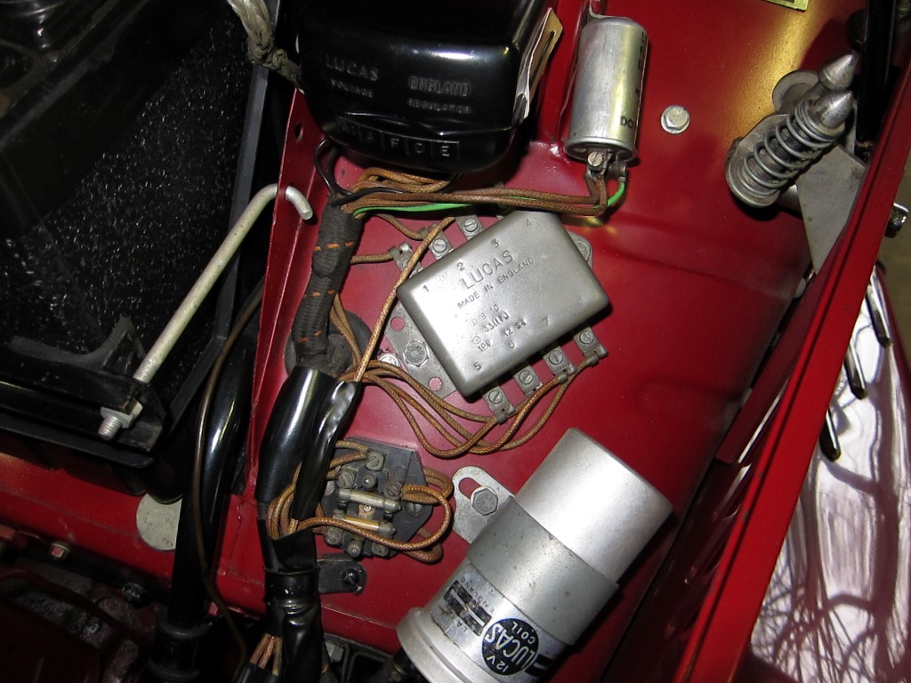
Protective Tubing for MGTD and MGTF Wiring
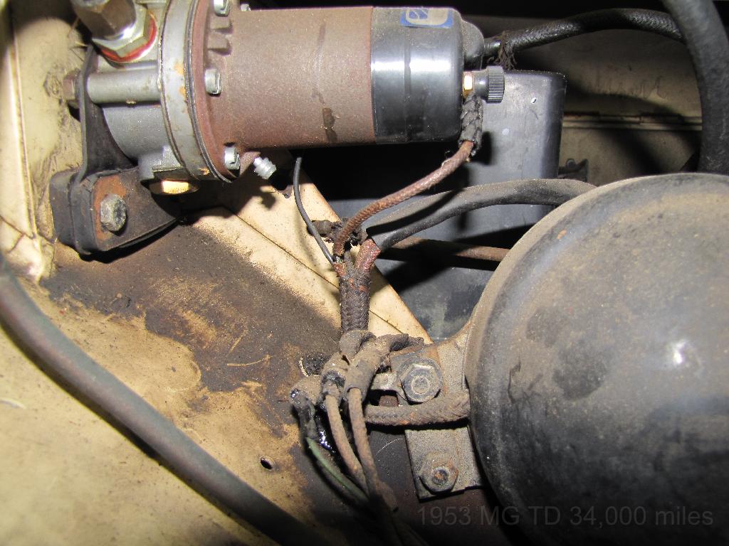
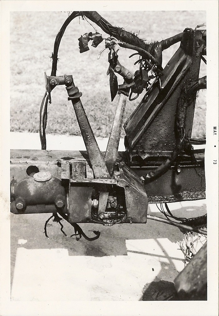
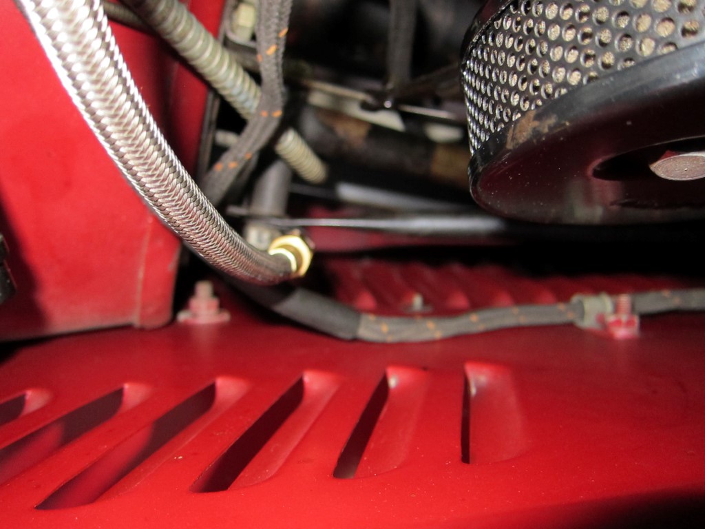
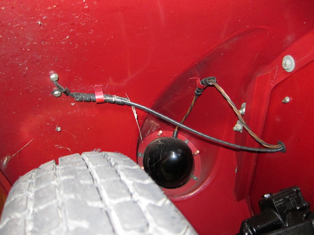
Various wires on the MGTD/TF harnesses received special protective coverings beyond the loom braiding. These were either from a wear perspective or to keep the environment or automotive fluids from damaging the wires and causing shorts. Many of these covers would need to be applied before the wiring connectors are added, especially in the case of the larger round connectors. Where available you can select the hyperlink on the location text to see an picture of the protective covering.
Not all cars had all of this protective tubing. I will use the ± character to indicate an item that may or may not have been in place for your car.
MGTD Protective Coverings
Location
Material
Dimensions
Comment
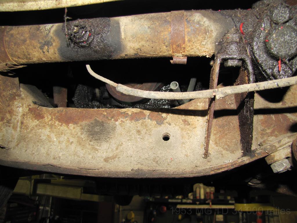
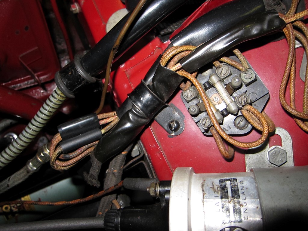
Over the coil to distributor white/black wire.±
Rubber
3/16" x 9"
On NA cars we see rubber on the ends of the cable (~1")

 It is all based on the braiding machine. This machine has 24 bobbins. 12 with cotton running to the RH side of the braid
and 12 running to the LH side of the braid. It works like a maypole, with the bobbins going around and under over each other,
just like dancers round a maypole. If I am using this / symbol it means the trace is running to the RH side of the braid,
( so looking from above this dancer is running clockwise (CW), when using this \ the trace is running to the LH side of
braid and the dancer would be running anti clockwise (ACW). When using this X symbol there is one dancer running CW and one
running ACW When using this //\ symbol there are 2 dancer next to each other running CW and one running ACW When
using / black / black /. There are 3 dancers running CW with a black dancer in between each.
It is all based on the braiding machine. This machine has 24 bobbins. 12 with cotton running to the RH side of the braid
and 12 running to the LH side of the braid. It works like a maypole, with the bobbins going around and under over each other,
just like dancers round a maypole. If I am using this / symbol it means the trace is running to the RH side of the braid,
( so looking from above this dancer is running clockwise (CW), when using this \ the trace is running to the LH side of
braid and the dancer would be running anti clockwise (ACW). When using this X symbol there is one dancer running CW and one
running ACW When using this //\ symbol there are 2 dancer next to each other running CW and one running ACW When
using / black / black /. There are 3 dancers running CW with a black dancer in between each.