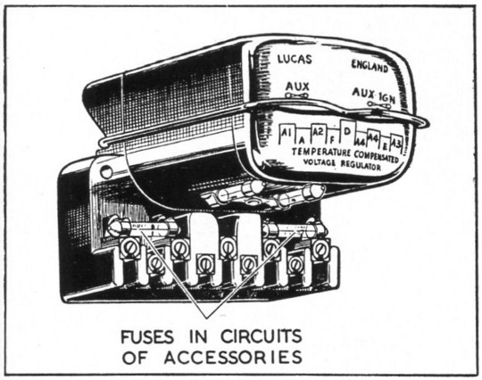
ELECTRICAL EQUIPMENT
Distributor Maintenace • Distributor,
Cleaning Cover • Cleaning Contact Breaker
AFTER FIRST 5OO MILES (800 Km.),
THEN EVERY 3000 MILES
(5000 Km).
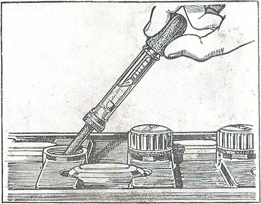
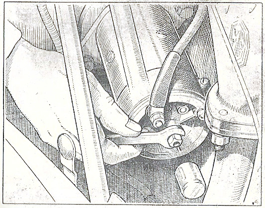
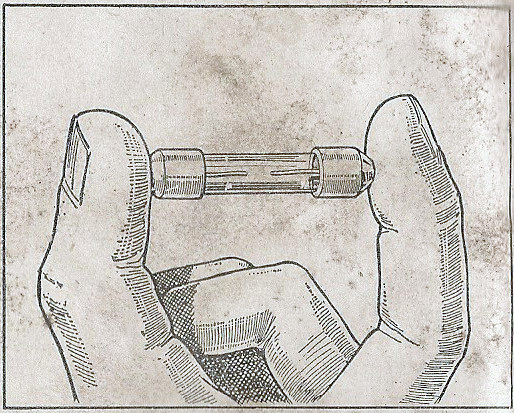
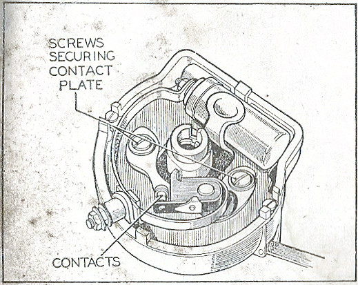
Remove the distributor cap and turn the engine by hand until the contacts are fully opened. Check the gap with the gauge on the screwdriver supplied in the toolkit; the gauge should be a sliding fit in the gap. If the gap varies appreciably from the gauge, slacken the two contact plate securing screws. Move the plate until the gap is correct and tighten the screws. The thickness of the gauge is .012 in. (.30 mm.).
EVERY 6,000 MILES (10000 Km.)
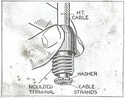
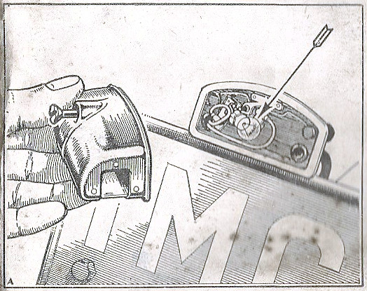
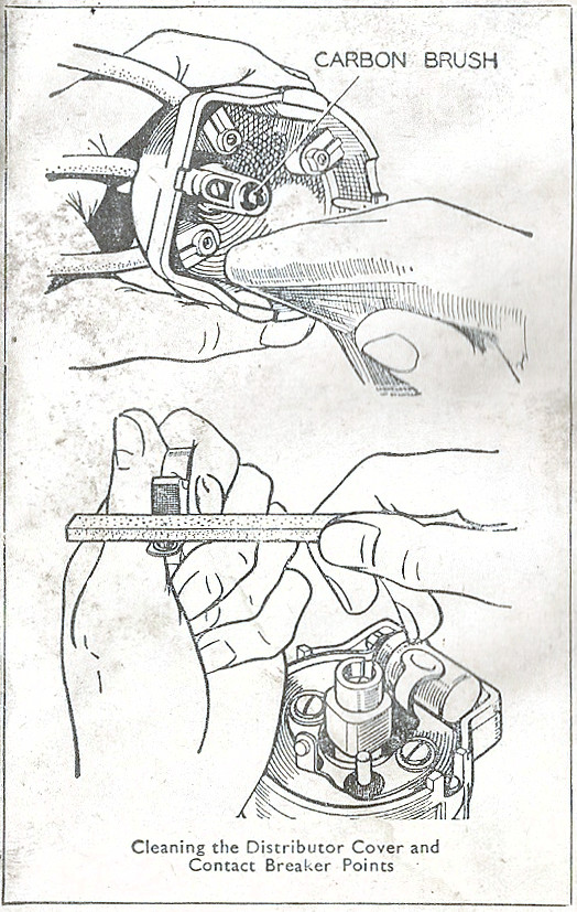
Wipe the inside and outside of the moulded distributor cap
with a soft dry cloth, paying particular attention to the
space between the terminals. See that the small carbon brush
on the moulding works freely in its holder.
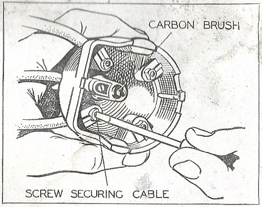
If the contact breaker points are burned or blackened, clean
them with a fine carborundum stone or with very fine emery
cloth. Afterwards wipe away any trace of dirt or metal dust
with a petrol-moistened cloth.
Cleaning of the contacts is made easier if the contact
breaker lever carrying the moving contact is removed. To do
this unscrew the nut securing the end of the spring, remove
the spring washer and flat washer and lift off the lever
complete with spring. After cleaning, check the contact
breaker setting on replacement.
53