THE CARBURETTERS
Cleaning the Filters • Adjusting the Slow
Running • Adjusting Mixture Control Linkage
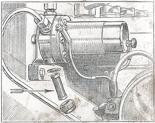
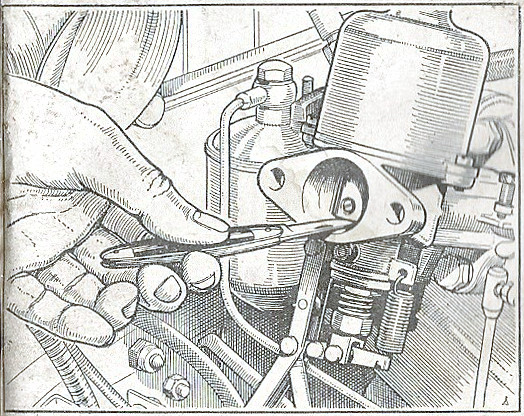
The Carburetter Filters
To ensure a free flow of petrol to the float-chambers the
filters should be removed at intervals of about 3,000 miles
(5000 km.) and thoroughly cleaned with a stiff brush and
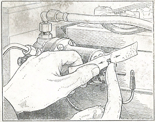
petrol. Never use rag. The filters are situated behind the
banjo-type union at the junction of the petrol pipe to each
float-chamber lid.
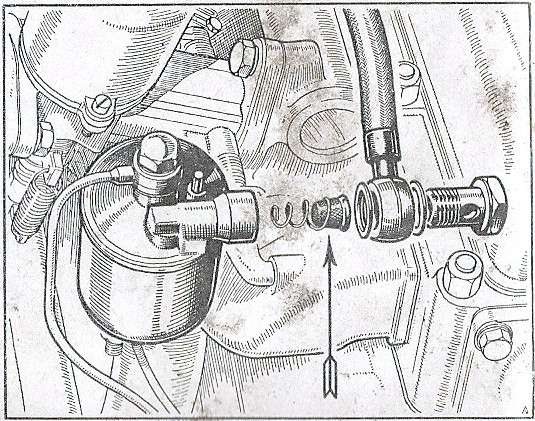
Replace the filters with their helical springs first and their
open ends outwards. Replace the fibre washers correctly.
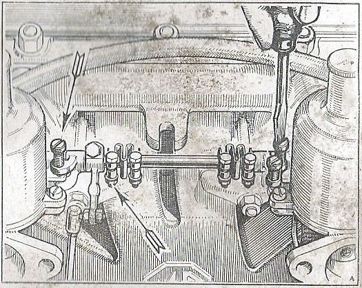
Slow Running Adjustment
Slow-running adjustments are carried out by adjusting the
position of the carburetter throttle lever stop screws, which
are spring-loaded, until gentle slow running is attained.
It is important that both carburetters are set exactly alike,
and you are advised to entrust this to an M.G. Dealer.
Make sure that there is a small clearance between the mixture
and throttle inter-connecting lever and its abutment screw.
Mixture Control Linkage
Adjustment
When the mixture control knob on the instrument panel is right
home there must be a small gap between the adjusting screw and
the operating lever on the front carburetter.
This gap regulates the action of the throttle and the mixture
control and should be set so that there is just clearance
between the end of the adjusting screw and the anvil of the
rocking lever linked to the jet operating lever.
50
THE CARBURETTERS
Adjusting the Jets
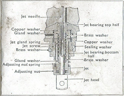
Adjusting the Jets
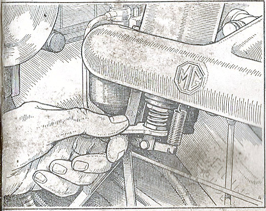
Run the engine until it attains its normal running
temperature. Set the slow-running screws on the carburetter
throttle actuating levers so that the throttles are both open
the same amount. This is indicated by the same suction noise
at each carburetter.
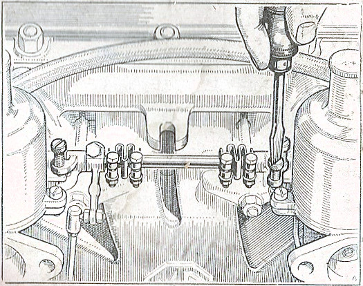
Disconnect the mixture control wire from the end of the brass
lever actuating the jets, and screw the jet adjusting nuts
well downwards. Note that the jet actuating levers are held in
contact with the jet heads by their return springs and must be
kept in contact the whole time.
The jet adjusting nuts should now be screwed inwards slowly (thus gradually weakening the mixture) until the engine idles evenly, firing on all cylinders regularly, and running at its best speed. This will be the normal slow-running position when the engine is hot and as the jet needles are the correct size the general performance on the road should be entirely satisfactory. Check by raising each carburetter piston 1/32 in. (.8 mm.). If the engine speed increases momentarily the setting is right. If the engine stalls the setting is too weak.
The mixture control wire may be reconnected when adjustment is satisfactory, care being taken to see that the control knob has ample clearance when the jet is in contact with the adjusting nut. Final adjustment for slow running is then carried out by adjusting each of the carburetter throttle lever stop screws an equal amount.
51