TAIL & NUMBER-PLATE LAMPS
Rear Lights
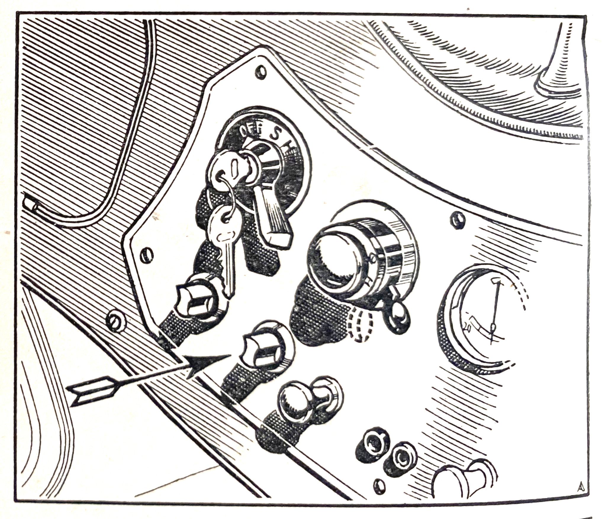
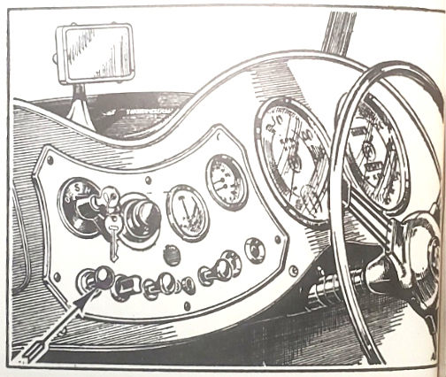
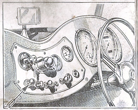
Number-Plate Lamp • Panel Light Switch
Rear lamps
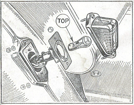
The tail- and stop-lamps are incorporated in the tail-lamp units, and use twin filament bulbs, the second filaments of which are automatically switched on when the foot brake is applied, thus providing a marked increase in the brightness of the lamps for warning purposes. It must be noted that the bulb is a special, one which can only be fitted the right way round to avoid a reversal of the tail and stop effects. The bulbs are marked "TOP" to facilitate correct fitting.
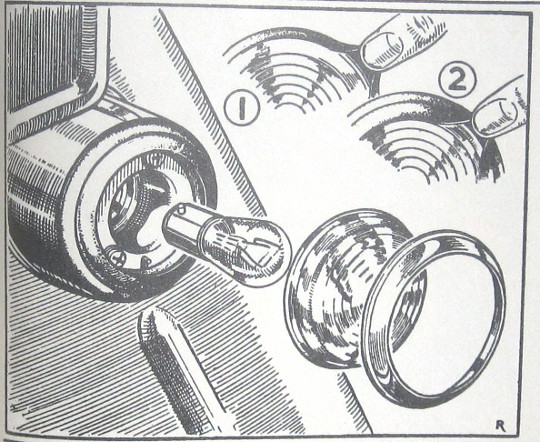
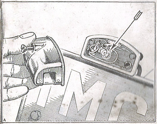
Number plate lamp
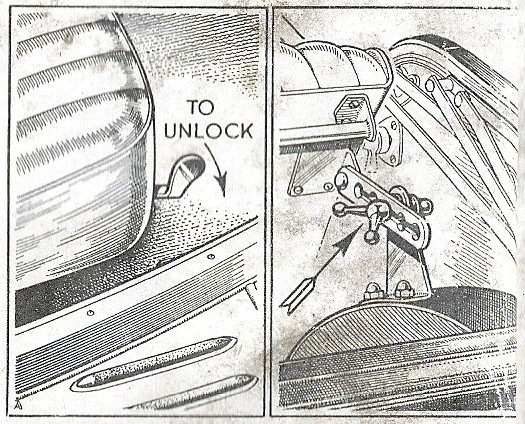
The number-plate lamp only operates when the side- and tail-lights are switched on. Access to the bulb is easily obtained by removing the cover, after un-screwing the securing screw.
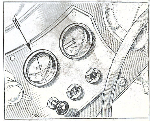
Panel light switch
The switch is situated at the extreme left of the panel. The light only comes on when the sidelamps are switched on, and the switch is of the knob type providing control over the lighting.
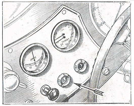
Panel light switch
The switch is situated at the extreme left of the panel. The light only comes on when the sidelamps are switched on, and the switch is of the rheostat type providing control over the brightness of the lighting.
12
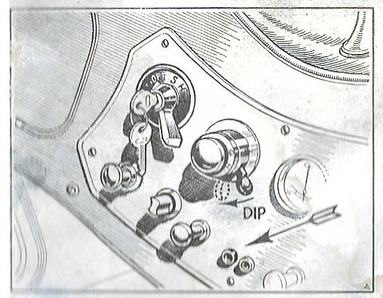
THE SWITCHES
Fog-Lamp Switch
Windscreen Wiper Switch • Inspection Light
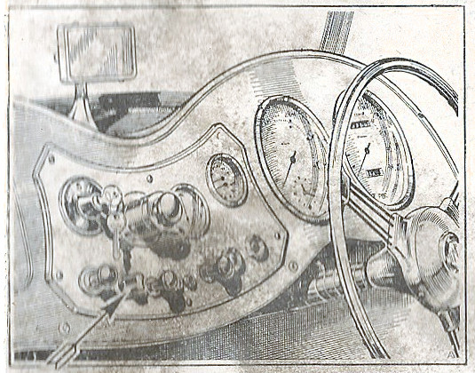
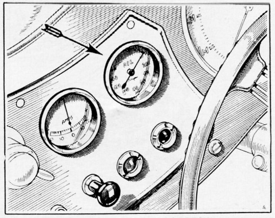
Fog lamp switch
This is on the left of the panel and the light only comes into operation when the switch is operated if the sidelamps are on. Remember it is illegal to use the fog-lamp except in conditions of fog.
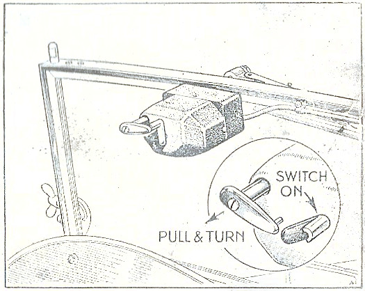
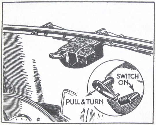
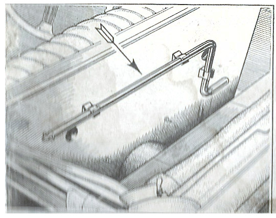
Windscreen wiper switch
The dual wipers are driven from the electric motor secured to the top of the screen. To operate, pull the seating lever towards you and move the switch to the right. The wipers only operate when the ignition is switched on.
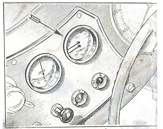
Inspection light
A two-pin socket is provided for an inspection hand lamp or map-reading light. The socket is on the instrument panel and is always "live".
13