Home History Details Technical Literature Entertainment Gallery Links Map


{short description of image}

TD Operation Manual - Preparing to Drive

This section begins with a table of general data and then covers topics such as preparing for the road and the MGTD's driving controls.

Prev Topic Contents Next Topic

PREPARING FOR THE ROAD

Filling Up with Petrol   •   Filling the

Cooling System    •    Releasing the Bonnet


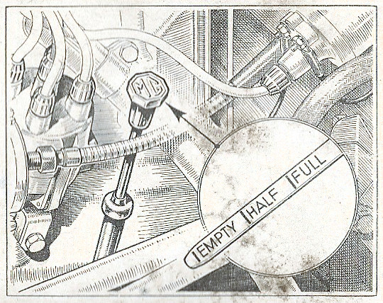
Filling up with petrol

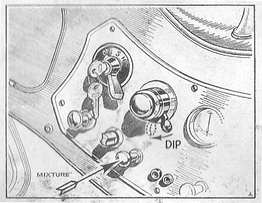
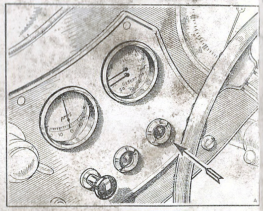
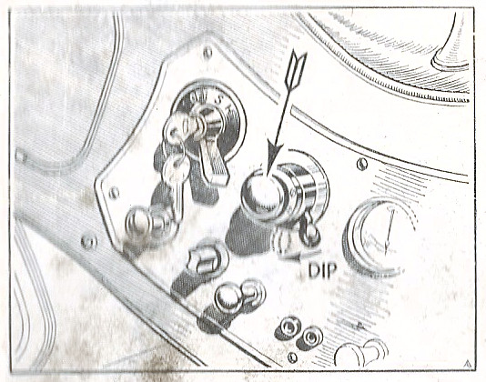
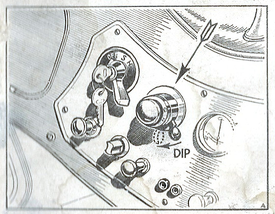
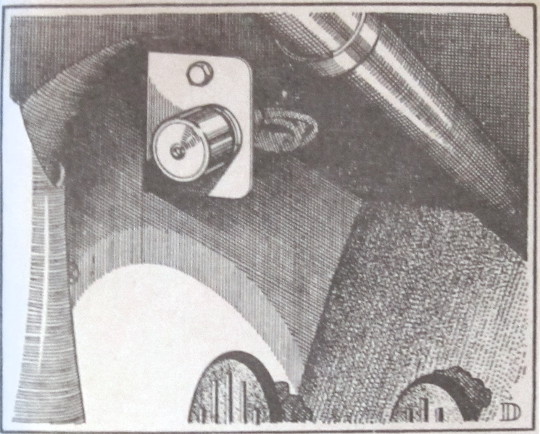
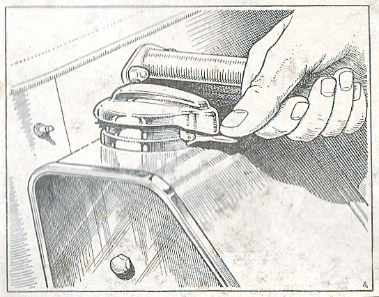
The quantity of fuel in the tank can readily be seen through the large filler which is situated on the left-hand side of the fuel tank at the rear of the car. Depress the small lever to release the cap and a downward pressure on the cap will suffice to close it. Tank capacity 12½ gallons (56 litres). A warning light on the instrument panel is switched on when the supply drops to approx. 2½ gallons (11 litres). (See page 14)


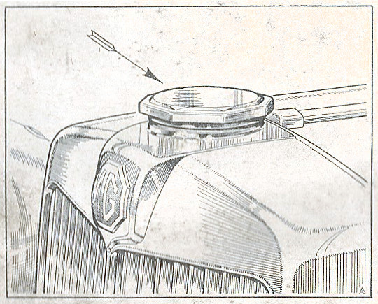
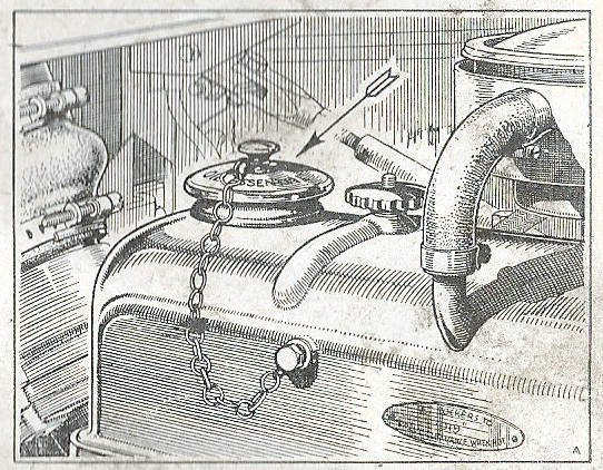
Filling the cooling system

The radiator should be filled to within ½ in. (13 mm.) of the filler neck. After a few minutes, more water will be required. This is because it takes time for the water to flow through the thermostat by-pass pipe. It is necessary to make good the water level and bring it up to the correct height again.
The filler cap is of the normal type and screws into position.


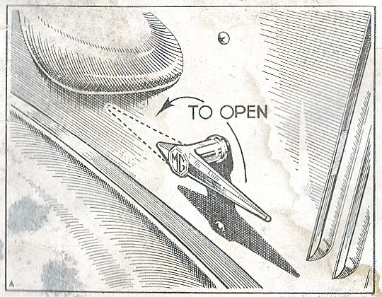
Releasing the bonnet

The bonnet is in two halves, opening along the centre line of the car. Two handles are provided on each side of the bonnet and these, should be moved upwards and forwards in order to release the catches.


5


PREPARING FOR THE ROAD

Checking Engine Oil Level

Filling Up With Engine Oil   •   Glove Box


Checking engine oil level

Check the supply of oil in the sump by withdrawing the dip-stick on the left-hand side of the cylinder block. Wipe the lower portion of the rod, re-insert it and withdraw it again. Oil will cling to the rod and show the actual quantity present in the sump. The normal oil level is indicated by the "FULL" mark on the dipstick. The engine must not be run for long periods when the oil level has dropped below the "HALF" mark.


Filling up with engine oil

The filling orifice is on the top of the valve mechanism cover. To open pull the small knob upwards and remove the cap. To lock the cap in position press the small knob downwards.
Clean fresh oil is essential and for a list of recommended lubricants see page 36. For sump draining instructions see page 37.


Glove box

This is situated on the passenger's side of the instrument panel and is opened by pulling firmly on the knob provided. When a radio is fitted the set and control panel can occupy the glove box.


6

PREPARING FOR THE ROAD

Starting Up When Cold

Starting Up when Hot


Starting Up

Cold. See that the gear lever is in its neutral position.
Pull out the mixture control knob and turn it 90° anti-clockwise to lock it in position.

Switch on the ignition by inserting the key in the centre of the lighting switch knob and turning it clockwise.

Pull out the starter switch knob smartly, when the engine should revolve and start.

Release the starter switch immediately the engine fires.

Gradually return the mixture control knob to the "OFF" position as quickly as the warming engine will allow. (See note on starter operation on page 56.)

Hot. See that the gear lever is in its neutral position. Switch on the ignition by inserting the key in the lighting switch knob and turning it clockwise. Pull out the starter switch knob smartly, when the engine should revolve, and start. Release the starter switch immediately the engine fires.


7


PREPARING FOR THE ROAD

Warming Up   •   Running In

Hand Brake


Warming up

It is extremely bad practice to allow the engine to warm up from cold by letting it idle slowly. The correct procedure is to let the engine turn over fairly fast (approximately 1,000 r.p.m., corresponding to a speed of 15 m.p.h. or 24 k.p.h. in top gear), so that it attains its correct working temperature as quickly as possible.


Running in

It is a great mistake to drive a new car either fast or hard (such as labouring up inclines on top gear). For the first 200 miles (320 km.) 35 m.p.h. (56 k.p.h.) must not be exceeded in top gear, 26 m.p.h. (42 k.p.h.) in third gear, 15 m.p.h. (24 k.p.h.) in second gear or 10 m.p.h. (16 k.p.h.) in bottom gear. The engine speeds should then only be increased gradually and progressively until at least 1,000 miles (1600 km.) have been covered.


Handbrake

The hand brake lever is located between the two seats. To operate, pull up and depress the thumb-operated knob to lock the lever in position. To release, pull up-wards on the lever, when the ratchet will automatically release itself. The hand brake is automatically adjusted at the same time as the rear hydraulic brakes, and needs no separate adjustment. The nuts at the base of the lever must not be disturbed.


8

DRIVING CONTROLS

Pedal Control • Gear Lever

Mixture Control


Pedal Controls

The pedal controls are arranged in the orthodox positions, namely the clutch pedal, brake pedal and accelerator, reading from left to right. Do not drive with your foot resting on the clutch pedal. It is bad practice and leads to rapid wear in the operating mechanism.

Gear Lever

The gear lever is centrally situated. First and second gears are selected by moving the lever to the left, and engaged by moving it forward for first gear and backwards for second gear. Third and fourth gears are selected by moving the lever to the right through the neutral position till resistance is felt, then forwards for third gear and backwards for fourth gear. To engage the reverse gear move the lever to the right of the neutral position until resistance is felt, apply pressure to the lever to overcome the resistance and then move it backwards to engage the gear. Synchromesh engagement is provided on second, third and fourth gears.


Mixture Control

The mixture control can be drawn out to give a rich mixture for starting purposes. It is locked in the open position by turning it anti-clockwise through 90°.

On no account should the engine be run for any length of time with the knob in this position. It should be returned to the "OFF" position as soon as possible. A little practice will soon familiarise the driver with the correct use of this control.


9


DRIVING CONTROLS

Ignition Switch

Ignition Warning Light   •   Starter Switch


Ignition switch

The ignition switch is located on the left-hand side of the panel and is operated by a removable key in the centre of the lighting switch. Turn the key clockwise to switch on. Do not let the switch remain in the "ON" position when the engine is stationary, except for short periods.


Ignition warning light

The ignition warning light glows red when the ignition is switched on. It will go out when the dynamo is charging adequately. It will glow red if the dynamo is not delivering sufficient current. It may glow when the engine is idling in traffic, but no harm will be done so long as the engine is running. On no account must it be allowed to glow for more than a few moments with the car and engine stationary. Switch off the Ignition immediately.


Starter switch

The starter switch is operated when the knob to the right of the centre of the control panel is pulled outwards, and it must be released immediately the engine fires. Operate the knob smartly in both directions. See page 56 for information on the proper use of this switch.


10

DRIVING CONTROLS

Horn Button   •   Headlamp and

Sidelamp Switch   •   DipSwitch


horn button

This is the raised black knob located on the centre of the instrument panel next to the ammeter.


headlamp and sidedlamp
switch

The side- and headlamp switch is on the left of the instrument panel and incorporates the ignition switch. Turn clockwise to operate. The first position marked "S" switches on the sidelamps, taillamps and number-plate lamp; the next marked "H" switches on both the headlamps in addition.


Dip switch

Dip switch

This is incorporated in the horn button switch and is clearly marked "D" for dip position and "H" for full beams.
In order to give the driver clear indication whether the beams are in the raised or dipped position, a warning light in the speedometer dial glows when the headlamp beams are in the raised position.

This is incorporated in the toeboard next to the clutch pedal and is foot-operated. It is of the single-acting, repeating type, dipping the beams on the depression, and raising them on the next.
In order to give the driver clear indication whether the beams are in the raised or dipped position, a warning light in the speedometer dial glows when the headlamp beams are in the raised position.


11


Prev Topic Contents Next Topic

Home | History | Details | Technical | Literature | Entertainment | Gallery | Links | Map

© 1999 - by Christopher C. Couper Page last modified: 2025/06/26