MGB V8 Conversions by Roger Parker |
|
|
Total Page
|
Fitting a V8 engine into an MGB History Some marriages are made in Heaven, but in the case of the MGB and Rover V8 engine, Ken Costello made this one in Farnborough, Kent. That the MGB was intended to receive a larger engine than the 1798cc ‘B’ series engine was always the case, from a planned, but stillborn, V4 engine in the early 1960’s to a 2.4 litre 6 cylinder ‘B’; series engine from Australia. Of course we all know about the final BMC dictate of using the 2912cc modified ‘C’ series engine, which promised lots yet delivered on balance less than the outgoing Austin Healey version. When the major company mergers took place in the late 1960’s BMC, first became British Motor Holdings (BMH), then British Leyland Motor Corporation (BLMC), later to be shortened to BL. Whilst most that surrounded this period of restructuring was bad for MG, there is one very bright jewel. This was in the form of the Rover V8 engine, itself a Buick design that had been dropped from the General Motors range. Whilst this engine may have been expensive to build, and not big enough (capacity wise) for the US market, it was an ideal size for the smaller engined European markets, to form the basis of an executive car engine. Certainly MG men were not slow to see various possibilities, witness the different designs put forward to replace the MGB. After all by 1970 the MGB was 8 years old, which was already longer lived than the preceding MGA. Money and politics played parts that left the MGB soldiering on with few mechanical changes, which left the market wide open for outside engineers to create conversions to improve the cars performance. As we all know Ken Costello engineered a very effective V8 conversion, that received rave reviews in many influential motoring journals. This led to the factory being instructed to do their own conversion, and as we say, the rest is history. More recently Rover, through the foresight of Heritage producing new MGB bodies, were able to produce the MG RV8, a car which my own V8 EFi conversion played an influential part of in the early development stages. When the factory V8 was being considered during the early 1970’s much was said about the lack of a roadster version. The official response was that the roadster shell was not strong enough, but in truth the main reason was again politics, with a roadster version being canned due to potential adverse sales conflict with cars like the Triumph TR6 and planned TR7, Jaguar E type and Triumph Stag. With the BL higher management being so apparently pro Triumph at this time it is easy to see why MG had such a raw deal, and could even give a possible pointer to explain the high pricing structure for the MGBGTV8. The arrival of the MGRV8 puts to bed once and for all the notion that the MGB roadster body is not strong enough for the V8. It also gives an air of respectability for a number of previously frowned upon modifications, the most obvious of which is the passage of exhaust manifolds through the inner wings. Many features of the RV8 can be carried over to home V8 conversions, without the associated high costs that also afflict the RV8. One thing that the high factory prices have done is to generate a very strong demand for conversions at more reasonable prices. Even so a properly done V8 conversion in an MGB is still not a cheap job, involving a minimum of around �4000 (based on 1997 prices), assuming that a great deal of work is self done. It can be done cheaper if you happen to be very lucky in parts sourcing, but with such a steady demand for V8 conversion parts prices remain firm. V8 Conversion basics So how do we go about doing a V8 conversion? Well the first question has to be how much money do you have for the conversion? Next is how much of the work are you going to do, which has a significant bearing on overall costs? There is the question of how technically minded you are, as this will affect the depth of the modifications you can complete yourself. All these and more have to be answered before you get going otherwise you are very likely to end up as one of those adverts in the MG Mart, ‘V8 conversion, unfinished project, best offer....’ To help you decide how best to achieve your desire to arrive at V8 power, the following general guidelines will be of considerable help. These notes are predominately based on UK conditions, which means UK spec right hand drive cars and availability of certain other cars as spares. Outside the UK local conditions and legislation will have a significant bearing on any conversion and there I would suggest that contact be made with others in that locality who have already overcome all those local problems. I categorise the conversions into two basic classes, chrome bumper conversions and rubber bumper conversions. These two groups I then sub-divide each into two further groups, depending on vehicle age. The one basic fact is that the newer the base car then the easier the conversion will be. I will cover each group starting with the easiest and working up to the most difficult. In all of these basis comparisons I will assume that the conversion involves transposing a complete range of factory MGV8 mechanical parts into the MGB body. If other components are being considered then the impact of their dimensions and operating features can very easily alter the basic guidance given here and would require an appropriate degree of alteration to the base plan, with consideration given to any knock on effects to other sections. Rubber bumper cars The easiest cars to do are the rubber bumper cars. These ‘rubber’ cars fall into two separate groups, cars built between Oct 1974 and Sept 1976, then cars built after Sept 1976. Conveniently the 1976 change point coincided with various other changes to the later range, including the new dashboard, ‘deck chair’ stripped seat patterns and adoption of the rear anti roll bar as standard. Post Sept 1976 cars (All VIN's from 410001 on) These late rubber bumper cars featured a full under bonnet pattern exactly the same as the factory MGV8. With the MGV8 kit of parts referred too earlier this would be a bolt in conversion! Oct 1974 to Sept 1976 cars (VIN GHN5 360301, GHD5 361001 to GHN5/GHD5 410000) Earlier rubber bumper cars feature very many of the parts common to the MGV8, but with one significant difference. This is in the position of the radiator, which follows from the earlier chrome bumper cars. The body is modified to accept the forward mounted radiator common to the V8 and late cars, but fitting these requires the removal of the existing radiator mountings from the inner wings and welding on the late type. One other point is that the chassis mounted engine mounting brackets should be the round single bolt type, common to the V8 and later cars, however I have seen examples where the earlier 4 bolt chrome bumper type were used. If these earlier types are fitted then they have to be removed from the chassis rails and the late type fitted. Once these modification(s) are done then the fitting of a V8 follows an identical route to the post September 1976 on cars. Chrome bumper cars The first point to make to those wishing to end up with a chrome bumper V8 is that they should consider starting with a rubber bumper car, and convert the external look from rubber to chrome bumper. This can be done relatively easily with one of the many ‘kits’ of parts that several MG specialists sell. If some sort of body rebuild is to be included in the project, which is not an unusual situation to find with MGB bodies, then this route can have many advantages. The main one would be if heavy cost items such as front wings were going to be replaced, as there is not any penalty by purchasing chrome bumper panels as opposed to rubber bumper panels, and the same applies to the rear wings. Full rear wings are expensive, but the difference between chrome and rubber bumper panels is negligible. The difference between rear wings is the area under the rear lights, chrome cars have a shaped metal section which forms part of the wing. Rubber bumper cars have this eliminated to clear the rear rubber bumper assembly. The lower rear wing repair sections are available for either application, so if you only need a lower repair then there is little extra metal required to complete the chrome bumper addition under the lamps, which most ‘kits’ contain. Now the preceding information is fine should you not yet own a donor car, but if you own a chrome car that you wish to convert, how do you achieve this? Firstly like the rubber bumper cars, the chrome bumper cars can also be sub-divided into two distinct groups. Those made from start of MGB production in 1962 to October 1967 (Mk 1), then between October 1967 and October 1974 (Mk 2 on). These two groups are easily identified as being ones that had the early three-synchro gearboxes and the later cars with the four-synchro units. The transmission tunnel being the obvious give-away, with the later cars having one with a completely flat top around the gear lever, whilst early cars had a pronounced hump in the area of the gear lever. (Only the later cars could feature the flat top centre console should you not be certain of your car.) The modifications required for this group are considerable and should only be considered by those with a good level of skill and workshop equipment. (Or at least with access to such skill and equipment) There are a number of common modifications required and others, which will be, age dependant. All models The bulk of the V8 engine in terms of extra width is highlighted by the need to remove a section of each bulkhead corner to allow clearance for the rear of the V8’s cylinder heads. The passenger side (RHD or LHD) is easy, as once the required clearance is achieved then a simple closing panel has to be made up and welded in. On the steering side there is the complication that the steering shaft passes through the bulkhead in the modified area and this has to be catered for during the modification. Whilst this isn’t a body feature, it has to be mentioned that depending on what steering system is being used, then this will have a critical bearing on the actual modifications to this bulkhead. The bulkhead area on the steering side can really follow two distinct routes. The first is the simple bolted clamp type of lower column mounting that is found in the early cars and which requires little in the way of body preparation, other than the actual clearance for the steering shaft. The other route is to use the later type of column, which utilises a three bolt fixing direct into the bulkhead. Obviously this requires some considerable care in positioning and then fixing, to ensure accuracy and strength. Once again the best reference is to use a rubber bumper car. Whilst engaged in this area the mountings for the upper end of the column have to be catered for. The column attaches to a triangulated bracket which in turn is bolted to the under dash scuttle bracing bar and the inner side of the bulkhead panel through captive bolts. Yet again the best route to follow to achieve this is to use a rubber bumper car as the pattern. With the bulkhead corners sorted out attention can move forward to the engine mounting affixed to the chassis rails. These are the wrong type and sit too high for the V8 so need to be removed. The simplest option is to use the genuine late rubber bumper mounting brackets, as these are the same as the factory V8 type, the RV8, and are available as a separate part. One point that must be stressed here is that the final positioning of these engine mountings will dictate the position of the engine in the engine bay. As such areas such as bonnet clearance, exhaust clearance and fitting of all other ancillary components will be totally dependent on the accuracy of this one fitting. Where alternative components are being used, such as injection or other non-original MGV8 carburration, then due consideration has to be given to the different dimensions, as there is very limited space under the MGB bonnet (hood). Immediately above the engine mounting on the inner wing a modification is required for exhaust manifold clearance, depending of course on what type of manifold you intend to use. Viewing any later rubber bumper/V8 will indicate that this modification is in the form of a longitudinal indent along the point where the inner wing changes from the angle to a vertical face just above the chassis rail. Moving further forward sees the need to move the radiator towards the nose of the car, again for engine clearance. The easiest route has to be to follow the V8/rubber bumper cars by using the genuine panels. These panels include the oil cooler tray and the under support panel, which also carries the oil cooler mounting. This panel has to be modified next to each end to provide access for the through bolt used to secure the bumper mounting brackets. The use of these panels enables the V8 radiator to be fitted forward and the oil cooler (if one is to be fitted) to be mounted underneath, which helps to improve radiator efficiency. Additionally the original radiator support bracket anchorages are now wrong and have to be removed. Once again the use of the V8/rubber bumper panels provides an obvious route, with one of these cars being used to provide a template and appropriate dimensions. All cars may also need relief to the top of the gearbox tunnel, under the dash area, depending on the choice of gearbox, especially so if the Rover SD1 (LT77) 5 speed is to be used. This modification is common to all RV8’s that use either a late version of the SD1 box, or the redesigned R380 5 speed box. Looking down an open transmission tunnel from the engine bay end you will see that the top of the tunnel ‘steps down’ as it narrows. This step has to be moved upward to the previous level for a width of approx. 3” and rearwards to where the top of the tunnel flattens out. This also happens to be where the old speaker frame is welded to the top of the tunnel. (In the passenger area) The front step is the most problematic as it has several seams joining and welded at this point. Careful drilling of spot welds, re-forming and re-welding is probably the simplest route. Early all synchro cars These cars have a larger transmission tunnel than the three synchro cars but even so the mouth of the transmission tunnel, particularly on the (UK) passenger side, provides tight clearance for the clutch housing of the gearbox. A section of the front of the tunnel has to be ‘dressed in’ towards the footwell to provide clearance. Three synchro cars The basic difference between these cars and all later ones centres on the transmission tunnel, and the fact that it is much tighter, having to accommodate only the later version of the MGA box. This means that choice of gearbox will significantly dictate the degree of work required, which must be anticipated as considerably greater than any later car. Earlier roadsters also used a banjo rear axle and the rear body pressings provide less clearance than found on cars that used the tubed Salisbury axle. This isn’t so much a problem if the MGB axles are retained, but where alternative axles are being used then specific clearance may be required. This area of modifications can apply to any MGB, whatever the age. The problem is simply that the V configuration of the engine means that the exhausts of the right-hand cylinders want to occupy the same space as the steering (vice versa on LHD cars). Clearly one has to yield and the simplest solution is to alter the steering. All V8 cars used a steering system that was visually very similar to the original system, and which was adopted for all rubber bumper cars. Therefore the system found on a V8 or any rubber bumper car can be used in any other MGB to provide the required clearances. The problems centre on the positioning of the steering universal joint, and to provide the exhaust clearance this has to be moved upwards, into the bulkhead. This involves the use of a longer pinion shaft in the rack, a shorter upper column to suit, and with the bulkhead modifications different upper column mounting points, as described. If the whole later type steering assembly is being used then the original dash will not be suitable since the later upper column is a safety collapsible type. This means that it is about twice the thickness to the earlier solid versions and so will not fit in the slot between the speedo and tacho positions. This also explains why V8 cars had the smaller 80mm diameter clocks, rather than the original 4” (100mm) ones. If the original style of dash, with the 80mm main clocks, is used then it will match the fatter safety style columns. (I can’t comment on the US style of dash) It is possible to use the original upper column as the splines are the same for all years, but the result may not be ideal as the steering wheel will be protruding a noticeable amount more into the car. It is possible to have this column shortened and resplined, BUT this has to be done properly. The problem here is that the column is tubular with the areas of splining slightly smaller in diameter than the main column. There is also a variation in the thickness of the metal at either end, with the splined areas being considerably thicker. The main column can be shortened and re-splined to suit, BUT, the tubing at the point for re-splining is thinner so when splined and clamped there is always the potential of fracture and loss of steering. It is possible to have this area fitted with a reinforcing ‘plug’ of steel so that when re-splined there will not be any possibility of failure in use. This combination of new and old pattern parts does provide a route to having the V8 along with a totally original looking exterior and interior! Another option originally used on the early Costello cars was to add an extra universal joint at the rack end. This added the same sort of length as yielded by the longer pinion shaft and so pushed the original steering joint into the bulkhead area and out of the way of the exhaust. The same comments re shaft strength apply here equally, but this has been proven to be reliable over many years’ in many cars. The last area of consideration has to be the front suspension/steering crossmember. Not only does this item support the rack, via two simple brackets welded to the frame, but it also dictates further engine clearance. The V8 and rubber bumper cars use the same crossmember. This is visually very similar to the chrome bumper, four cylinder cars, except for two welded on spacers that push the car body and crossmember apart by about an inch. This helps provide much needed clearance for the V8 sump, which would otherwise need modification to the pan to enable it to fit. (Modifications dependant on which sump is used). Not only do we have sump clearance but also the angles for rack mounting are different, so the brackets on these crossmembers are different to allow the correct rack mounting angles to be achieved. What has to be borne in mind is that when a later (longer pinion) rack is used with a chrome bumper crossmember then the angles of mounting are wrong and the pinion shaft will point into space above the whole bulkhead area! The crossmember mounting brackets can be altered to suit, but this is a job that has to be done properly. This is another reason why the Costello cars use a second universal joint! Obviously a very important area especially since even the most basic of V8’s can double the torque and power! The standard MGB system was good for the day and the ‘B’ series engine performance, but even in brand new condition can only just be described as adequate today. So what can be done? Quite a lot, fortunately. The first consideration is to view the expected power of the final engine you are going to use. If this were going to be a near standard 3.5 engine then following the route of the factory MGV8 would be adequate. This route involves the use of front discs the same diameter as the original MGB disc, except for being 30% thicker at 12.8mm (1/2”). The original caliper can’t accommodate this thicker disc since the caliper doesn’t split down the middle, unlike modern multi piston caliper. This means that the machined bridge area that caters for different disc thicknesses can’t be altered and so an alternative has to be found. The MGV8 used a one off caliper which used the inner ‘half’ of a caliper that had a wider bridge, with the original pattern MGB outer ‘half’. This inner half was commonly found on many big Triumph saloons of the 1970’s and copies can be made up using these two basic components. It is interesting to note that this pattern of brake was to be standardised on the MGB at the time the car was axed, some very late cars could even have such a set up as standard. The next alternative would be to go to a specialist and uprate the brake pad /shoe material with some ‘heavy duty’, ‘mild competition’ items. These will help but can have adverse effects during cold operation along with heavier disc/drum wear. Another modification is to have the front discs cross drilled in an effort to increase the surface area for heat dissipation, this can provide a slight advantage, and it does help to prevent glaze build up when using ‘harder’ pads. One point here is that the chosen road wheel will have a considerable bearing on the rate at which the generated heat from braking can be dispersed to atmosphere, with the more closed designs being worse. (Discs can also be ‘grooved’, and if done ensure that the edges are radiused to relieve heat stress areas.) From this point we move into the area of some serious brake modifications. The RV8 uses a very effective ventilated disc along with a ‘four pot’ caliper. (The caliper has four pistons, two either side of the disc) One point to make is that there are a number of specialists offering vented disc conversions, but do be aware that any conversion should use a disc of at least the same diameter of the original, (10.75” or 273mm) or very close to it. If the conversion uses a disc of a smaller diameter then the extra surface area of the vented disc will be partially lost by the reduction in diameter. Not only that but the diameter of the disc has a significant bearing on the pedal pressure required, and a smaller diameter disc operates with a smaller leverage effect! The RV8 uses a disc of 270mm (10.6”) which is so close to the original size as to effectively lose nothing. RV8 parts are available but expensive, but there are alternatives to achieve the same ends. All brake manufacturers make a range of parts that have as many common features as possible to reduce production costs. Over the years many factors and dimensions remain constant and this is to our advantage. In the MGB range, as well as very, very many other cars, things like offsets and mounting lug dimensions remain the same. Looking at other cars we can find a number using very similar four pot calipers with the same basic dimensions as the MGB. Lockheed, who are the OE supplier of brake parts for the MGB, along with Girling, ATE, Bendix and others all have a comparable caliper in the range. Keeping things simple I look at the RV8 caliper and find that it is just a current production item. I then look at the Austin Princess/Ambassador range of ‘Sloth’ saloons and find that they are fitted with a four-pot caliper of almost identical design to the RV8. With some very minor changes to the twin pipe feed arrangements, these can be bolted to the MGB uprights with the use of very late Triumph GT6 caliper bolts. They fit straight over the genuine MGV8 solid disc and with standard pads provide about 15% greater swept area. The overall surface area of the four pistons works out to very close to the original two MGB ones so fluid displacement during operation and pedal travel is not a problem. The biggest advantage with these calipers is that they split in the middle of the bridge area and the factory approach to the use of thicker vented discs is to use different thickness bridge pieces. These are readily available from brake specialists along with all the other parts needed to complete a safe conversion. My own conversion follows this route along with the use of a pair of discs originally intended for use on the Peugeot 505 Turbo. They have the same basic dimensions as the MGB discs except that they are ventilated. Hub size and bolt patterns are different and require some specialist drilling to convert to MGB, but once done they bolt up in the same way as the originals. I am using 14” diameter wheels of the knock on alloy design; fitted to a standard wire wheel hub and I have no clearance problems. The standard non vented set up for these calipers also fits without clearance problems with standard Ro-style and original wire wheels, but with other wheels careful checking will be needed to ensure enough clearance is present. On the same theme there are a number of brake specialists offering much more exotic brake conversions with larger and thicker discs, once again clearance would have to be checked carefully before committing any major expense in that direction. As a guide up to about 275mm will fit under a 14” diameter wheel, up to about 290mm under a 15” diameter wheel, and any bigger involves moving into the realms not normally connected with MGB’s, but anything is possible! The standard braking bias involves the huge majority of braking effort be done by the front, something in the order of 80% vs. 20%. The original drums are quite large in diameter and provide a large surface area of shoe contact. This provides more than adequate retardation for a road MGBV8 and only in very few cars would anything else be required. The factory MGV8 cars although being GTs used the roadsters smaller diameter wheel cylinders to reduce the possibility of rear wheel lock up during heavier braking. This should be carried over to conversions as well. This OE set up also provides a simple and effective handbrake. (When the cable isn’t seized!) The other factor now becoming more common is that with many different types of open design wheel being used, along with the acceptance that performance cars always have an ‘all disc’ set up, there is an increasing demand for the rear to be converted to disc. A number of cars have been so converted, not to any regular pattern, but rather with what is available to that particular owner. Once again the specialists are offering complete conversions, and for those interested in doing their own, do bear in mind the added complications that the handbrake presents. One avenue that does seem to crop up again and again is the use of calipers found on rear driver Granada (1985 to 1995) and Cosworth Sierra (same caliper). Use of the calipers found on the 4x4 version of both these is also muted. I consider that this is due more to the fact that there are many more conversions done for Fords, so the specialists are more familiar with parts from these cars and have ready access to them, rather than a failure on the part of alternative parts. As is the case with the fronts much of what brake manufacturers make revolves around many common factors, so I expect many other parts to be suitable for use, for example Rover 800 parts, which are readily available and cheap. (In the UK) This is one area where many owners do such a lot and achieve next to nothing! This applies equally to any MGB, not just to V8 conversions. The reason is quite simple and is due to owners having a misguided view of the state of their own cars original suspension, and their perception of the capabilities of the standard suspension in tiptop condition. With the newest cars (RV8 excepted) being now 18 years old it is fair to expect that some general wear will have taken place. Furthermore those cars with just a few thousand miles use will also be suffering since lack of use doesn’t stop time from causing changes to the components, reflected in poorer performance. One fact that I have come across many times over the last few years is that cars freshly rebuilt with quality components display very good ride/handling traits, but they are almost always outclassed by the few cars that are in regular daily use. I maintain several cars that are still used as normal daily cars in all weathers and these cars have a very supple ride with smooth controllable handling. The suspension on each of these cars is subject to ongoing maintenance, so that at any given time there will be some parts which are much newer than others. This means that even these cars will not be able to display the best possible characteristics. This forms the basis of what I see as the problem. Owners assess the performance of the MGB suspension based on an incorrect and variable base line. A car subject to a complete rebuild with all new components will, after a few thousand miles of regular use, settle to provide the best that the standard suspension can offer, which for many will be way beyond what their expectations of the system are. This is why I always recommend a start point close to the original standard specifications. For a V8 conversion a couple of very pertinent additional factors have to be considered, which is of course the torque and power of the engine. The MGB suspension is best described as ‘functional and well proven’. The front being much more advanced in design than the rear, even so it is now over 50 years since the original version of this suspension first appeared on an MG! With the advances over the last 20 years in suspension and tyre design, we have all now become familiar with even the most mundane of cars being able to offer a ride and handling package that will always be far in excess of what the MGB design can give. This has led to expectations by owners that can never be met, but many try to modify to achieve this. Once owners accept the design limitations then a sensible approach can actually achieve some worthwhile benefits. The front suspension is of an independent design with double wishbone, coil springs and a double arm lever damper that acts as a top link as well. In a V8 conversion the spring rate has to be balanced with the rear, in order to maintain a front to rear balance, so more on that later. The lower arm inner bushes are made from a flexible rubber, which is prone to degrading, and does allow quite a degree of compression that leads to suspension distortion. The original factory V8 used a much stiffer bush that was also of a one-piece construction rather than two, and is one used in the RV8 for the same purpose! These are well proven items that also allow for retention of a reasonable ride with good noise and shock insulation. Owners often overlook these latter points when they change to one of the many firmer alternative bushes available from specialists. (They then wonder why the car is so hard and crude even one the smoothest of surfaces) In addition to these long established routes there is the relatively new addition of Polyurethane suspension bushes, which the makers/suppliers make various claims for. Owner comments do seem to be supportive of the general improved handling claims The dampers can be uprated with different valves, but be wary of those rated at over 33% stiffer, since it is easy to reach the point where the dampers resistance to movement is such that it doesn’t move. This means that the tyre sidewall becomes the only effective spring medium, commonly referred to feeling like a go-kart, which is exactly what it is! The original lever dampers can have the damping function removed and replaced by a telescopic kit. This retains the original damper as the suspension top link, with the new damper mounted on the one side of the suspension. I personally have never been happy with the apparent unbalanced nature of this set up. We now move onto the more comprehensive kits and there are several alternative suspension kits available. The first on the scene was the Ron Hopkinson kit, from Derby MG parts specialist. Created with help from Harvey Bailey, a well-known suspension tuner, the kit involves the replacement of the front anti-roll bar with a thicker one, and adding one to the rear suspension. (A Mk2 version with improved link arms and joints is available) Later this was developed further with the addition of a modified front crossmember, replacement top suspension link replacing the lever damper and new Bilstein telescopic dampers mounted centrally. This kit was complimented with matched Bilstein dampers to the rear. I have experience with one 4.3 litre GTV8 so fitted and the effect was quite impressive. The next front alternative is the Moss Coil Over conversion. This follows a similar route to the Hopkinson kit, but here it appears competition design components are utilised to provide a coil spring over a telescopic damper. With a wide range of easily adjusted spring platform heights this kit enables a wider range of ride heights to be easily set. Drawback may come from the fact that it uses components originally intended for competition use and the change to long term road usage may show some problems not encountered in the competition environment where mileages are less and adjustments frequent. The ultimate for MGB front suspension has now to be the availability of the RV8 front suspension as a kit for both disc and wire wheeled MGB’s. This assembly comes with the ventilated front discs and four pot calipers of the RV8 and is quite complete. At a price of around 1500 UK pounds, before VAT, it should be. Moving to the rear suspension sees the need to consider not only normal suspension considerations but also the location of the axle and transmission of V8 engine torque. Each of these areas will interfere with the others making the creation of the ideal set up almost impossible. Truly exotic full independent rear suspensions can be created, as can the use of modified Jaguar I.R.S. but this is a very complicated process especially in the setting up process. Probably the best-balanced alternative is to view the RV8 and adopt a similar set up. In the RV8 and many previous conversions, the one main problems is that the use of simple semi-elliptic springs means that the spring has to not only distort in reaction to road surface irregularities, but it also locates the axle. Then it has to resist the torque reaction of the V8 engine. If all three functions have to be done at the same time it is obvious that the system will not be able to perform too well. The need to provide axle location and torque reaction requires that the spring is much stiffer than would otherwise be the case for just a suspension medium. This stiffer spring then has a negative effect on the way the car reacts to road surface changes and being much stiffer it is also in conflict with the softer front springs. One way of reducing the problems are to transfer some of the axle location and torque reaction functions to a pair of anti tramp bars or torque reaction bars. These are mounted to the body by the front mountings of the rear springs and connect to the axle via the brackets that hold the spring to the axle. This has been adopted by the RV8 along with the use of a twin leaf low friction spring. In conversions some experimentation with spring rates can be followed, but the original spring rates should now be quite practical. If stiffer springs are used at the rear then these should be matched with the front also. Damping at the rear was originally by a single arm lever damper and once again these can be uprated like the fronts. Many cars have come in for a rear telescopic damper conversion and this is a well trodden route. My experience indicates that the dampers commonly available are too ‘hard’ even when the settings are wound right off. Of the telescopic dampers available I do favour Koni. Another problem that is found on V8 conversions will be the telescopic damper lower mounting. This conflicts for space with the larger V8 exhaust and usually requires some careful re-routing of the rear sections of the exhaust. Another problem found with V8 torque can be the regular failure of rear suspension rubber components. The spring pads seem especially prone to this and consideration should be given to use a more resilient material. Remember though that too hard a material will transmit much more road shocks through to the car’s body. Wheels and tyres are often a very personal choice and it is true that the biggest visual change that can be done to any car is to change its wheels. The basic choice is between wire and disc wheels. Experience with wires shows that only the visible aspect is in the positive, with virtually every operating aspect being negative. The original 60 spoke wires are simply not strong enough for long term absorption of V8 torque and will flex, distort and eventually fail. Uprated 72 spoke wheels are able to absorb the torque, but will also distort in use and so balance will be a problem. If there is a desire to use tyre profile of less than 70% aspect ratio then the need to use tubes in wires raises problems in obtaining the correct size of tube. Avon do some for the 15” wires that Morgan use with 60% aspect ratio tyres, but beyond that there is very little. On the positive side the amount of air that passes through the wire wheel will add very considerably to the brake efficiency, except in heavy rain when water will initially reduce brake response. The ideal choice has to be an alloy wheel of whatever design suits the owner. Size of the wheel should be limited to 6” width where standard body lines are retained. This applies to either 14” or 15” diameter but note that the maximum width of tyres will vary depending on the diameter, profile and make of tyre. The restricting factor is the arch clearance at the rear where only tyres of a nominal 185/70 or 195/60 section can be considered, before body modifications are needed. (65% profiles can also be considered, but check clearances) It is also true that the wheel offsets will also add to this equation so whatever your choice do step very carefully. Cars fitted with the Sebring or RV8 types of body kit have considerably greater clearances and here the temptation is to fit much bigger and wider tyres. The suspension and steering were designed during a period when ultra low profile tyres and very wide wheels were not available, so bear these factors in mind when selecting these and try and remain a little conservative. The steering weight and feel will be better for it. Engine History and Specs The preceding chapters have developed a body and chassis capable of taking the vast power and torque increase that the V8 gives, It is now time to look at this engine and the options open too us. In standard form there are several different configurations and each has it’s own minor differences. It started with the Buick family of engines from which the Rover V8 emerged. I know precious little in detail of these engines and in the UK they are quite scarce. In the US they are much more common as are the direct family variations of different capacities. Those wishing more detail on these would be best advised to contact the North America MG V8 Register in Rocky River, Ohio. (E-mail Error! Bookmark not defined. ) who have much information on file. The Rover V8 as we know it first appeared in 1967 in the Rover P5B (The 3 litre body with the B a reference to Buick) and was apparently very similar to the previous Buick versions. It had a capacity of 3528cc via a bore of 89mm and stroke of 71mm (figures rounded off for simplicity) and provided true excitement to a range that was previously described at best as being ‘unexciting’. The engine then found its way into the P6 range (Rover 2000) and Range Rover, and did the same for those models too. With a compression of 10.5 to 1 it was quoted as producing a number of different levels of power, but for simplicity you should expect that this was around the 150bhp mark. This figure will be accurate enough to compare with later and current power outputs, where the method of power measurement is more restrictive and representative of what you see with the engine installed in the car. The lower 8.13 to 1 compression Range Rover spec engines gave about the 135-bhp mark. Torque would be around 200 ftlbs. An important fact, and I say fact, as this is Land Rover information, is that from October 1970 (nineteen seventy) ALL, yes ALL, V8’s were made with components that were compatible to the use of unleaded fuels. As Land Rover have always been responsible for the manufacture of the V8 from day one to today in their Acocks Green factory, the information is applicable to all Rover V8’s. If the compression ratio is below 9.0 to 1 then no changes are needed for the use of UK 95 RON unleaded, and just retarding of the timing by three to four degrees if your compression is higher than 9.0 to 1 and below 10.25 to 1. For other fuel grades different settings may be required. The 3.5 was used in the 2591 MGBGTV8s from 1973 to 1976 in a form that was often quoted as being Range Rover specification. This was incorrect and probably due to the fact that the power outputs were similar at 135 (Range Rover) and 137bhp. (MG) In fact the engine was much more akin to the Rover saloons with a unique compression ratio of 8.25 to 1. 1976 saw the first major revision of the V8 under the Rover banner when the SD1 saloon range was introduced. Many detail differences were adopted and these were added to over the following years. Range Rovers adopted a similar series of modifications in 1978. The SD1 power output remained similar at 155 bhp (150 for the Federal injected cars) on a new compression of 9.35 to 1. When the range Rover adopted those engine modifications, it retained the low compression for several years, then with greater emission controls the power went down to 125 bhp. The next real development was the arrival of the Vitesse using the previous Federal units injection system in a three piece performance inlet casting. Power was quoted at 190 bhp and this would be accurate for the original versions, but later production versions reverted to a standard camshaft so power would be slightly down, by about 10 bhp. Compression ratio was increased to 9.75 to 1 for this engine, and there were some port modifications in the heads. In 1985 the Range Rover adopted this engine with a softer cam and 9.35 to 1 compression ratio to give 165 bhp. Torque for these injected engines was about 10% more than the carbed versions. Next stage was the arrival in 1988 of the large bore (94mm) engines that gave 3947cc with the original crank. This was for the emission strangled US market where the 3.5 was too restricted. The following year the 3.9 as it is known, appeared in the UK Range Rovers with 184 bhp and around 20% more torque, throughout the whole rev range. The arrival of the 3.9 was also accompanied by the change of injection system from the early Lucas Airflow Meter System to the more powerful Lucas Hot wire system. This system offered some power advantages over the earlier system and was also seen on the new Discovery in 3.5-litre form. Next development was the long wheelbase Range Rover when the extra bulk of this model was compensated for with the lengthening of the crank throw to enlarge the capacity to 4.2 litres. Externally there were no visible differences other than ‘4.2’ cast into the Plenum casting. Compression was 8.9 to 1 and power rose slightly to 200 bhp, torque took the biggest jump by another 10%. The 3.9 litre in Range Rover spec was used in the MGRV8 in 1993 and has been used by many other small manufacturers too. In 1995 the current range of engines was heavily revised for the new Range Rover and at this time a new large capacity of 4.6 litres was created. These two new engines have so many differences to the older units, such as new block, crank, oil pump, ancillary castings, to name just a few, that it makes them an impractical unit to use. Unless you have obtained a complete unit with ALL of the new GEMS 8 total engine management system. Even then the relocation of parts such as the oil pump (to on the nose of the crank) would lead to clearance problems that would require a completely new set of solutions. (Please note that some of the last of the Classic Range Rovers [with air suspension] used some of the new engines parts, such as oil pump and new front cover casting, and these were still shown as 3.9 series engine) A word on engine descriptions will be of use. The latest Range Rover/Discovery engine is termed as the 4.0 litre. It does in fact share the same 3947cc of the earlier 3.9, but the use of 3.9 and 4.0 designations is used to provide a clear definition between them to reduce confusion in view of the substantial differences between them. The 4.6 version as found only in Range Rovers to date, uses the same new configuration with a much longer throw crank with the 94mm bore. Any of the earlier Rover V8 engines can be used as the base engine for a MGV8 conversion. By far the most popular engine now is the 3.9, and is the one with the best bore to stroke ratio. In standard form it will provide more than enough power for most people, but if this isn’t enough it can be easily and very reliably tuned to give an easy 250bhp or more. Being that it has been the standard unit for base production purposes for the last 6 tears or so means that it is now the most common complete and useable engine seen in adverts. I consider that the 3.9 capacity is the optimum for the Rover V8. Any further capacity has to be achieved with an increased stroke that reduces the engine’s smoothness, or with larger pistons (up to 96mm) that stretch the liners to the absolute limit. Another factor is that the cylinder heads are designed to work with a 3.5 litre engine. A 3.9 bore reduces the valve shrouding and increases flow without any head modifications, but ultimately the heads will not be able to supply large capacity engines as efficiently as other comparable capacity V8’s. It is possible to bring earlier 3.5 litre engines up to the 3.9 capacity by fitting the 3.9 liners and pistons, but this is really only practical on 3.5 blocks made during the mid to late 1980’s. Earlier block may well suffer reliability problems so the work isn’t worth the effort, when 3.9 engines appear quite regularly at reasonable prices. (Look in 4x4 magazine adverts to see parts removed when big diesels are fitted to Range Rovers) Mention must also be made of a variant of the Rover V8 that was fitted to the Australian Leyland P76 saloon. This had a capacity of 4.4 litres and was an engine that occasionally found it’s way into some Range Rover conversions in the UK. Otherwise this engine is one that was mainly restricted to Australia. Engine Fitting Whatever the choice of engine fitting to the MGB follows the same route. The common one is to use the same engine mounting plates and rubbers as found on factory V8s. This makes this area as simple as an OE car. Alternative mounting plates are available from specialists which may differ in detail, but which follow a similar theme. The RV8 mountings can also be used, if you are prepared to pay Rover prices! Fitting the engine into an MGB presents several problems depending on the age and specification of the engine you have. All engines have to be fitted with an adapter to the base of the oil pump to clear the steering rack. The oil filter is remotely mounted and in factory cars there is an oil cooler in the circuit as well. I question the need for the cooler on most MGBs, and in the V8 application the RV8 seems to support my view, in that it doesn’t use a cooler. Before discarding the cooler though note that the RV8 features a better radiator, better airflow through the engine bay, and has the benefit of modern oils. The modern oil is available to all, but I would introduce better than original cooling capacity before discarding the oil cooler, especially on cars used in hot climates and for competition. The oil pump is cast within the front cover and it is worth noting that SD1 and later engines use a pump with about a 20% greater flow rate. The front cover will vary depending on age and application and apart from carrying the oil pump it also carries the water pump and distributor. Early saloon cars and the MGBGT V8 use the same water pump with a short nose, later SD1 pumps have the same base but an extended nose. Range Rovers have always used a much larger pump that is totally different to the saloon car versions. This Range Rover pump is used on the RV8. The distributor only presents a drive problem, in that the post 1982 ones are best, yet can’t be fitted to pre 1976 engines unless drive modifications are made. (The drive connection between the pump drive and the distributor drive is a simple slot and peg design, but post SD1 engines drives are reversed. The SD1 series front cover used to be the best option, in that it gave the best standard oil pump, better crank pulley oil seal, and best standard Lucas distributor. (The Constant Energy type) With this cover the standard pre-SD1 crank front pulley, alternator mounting and MGV8 water pump could be used with the standard MGV8 fan belt. All parts being off the shelf items that can be easily serviced and obtained. Now the situation is slightly different since the RV8 created the further option of using basic Range Rover pattern parts, which being newer are likely to be more readily available for many years to come. Certainly some of the original pattern MGV8 parts are becoming more difficult and expensive to locate. One common factor for all engines is that the original oil filter position is trying to occupy the same space as the steering rack! Something has to give, and it isn’t the steering. All engines can be modified with an adapter that replaces the base of the original oil pump, leaving just a compact and neat unit with two hose connections. In the original MGV8 these feed a remote filter head and an oil cooler, yet the RV8 only uses the filter head, as touched on earlier. Whatever choice is made it is far better to follow with the complete list of parts rather than to try and mix and match. For example the pulleys for the alternator, water pump and crank pulley wouldn’t align unless all parts are from the same source. A further consideration in this area is that when the RV8 style of front pulley parts are used then the crank pulley will probably contact the front anti roll bar, especially if this is a thicker than standard part. The RV8 gets round this by using a bar with a section bent forward to clear. This bar could be used or an original bar bent by a spring manufacturer. (It will require considerable force to bend properly) Alternatively the mounting positions for the bar on the two longitudinal chassis members can be repositioned slightly forward, pulling the bar forward. The amount that can be achieved by this method is limited to a few millimetres. Most of the problems have now been overcome and the engine will be a bolt in operation into the body. Only overall engine height may present problems. The induction system is the main theme here and will be covered in a later section, but also the rocker covers and attachments may give problems. The original MGV8 used covers of the same pattern as the original pre SD1 Rovers without the word ‘Rover’, but with ‘MG’. These are rare to find second hand but are available from specialists. In either case they are expensive but give a certain extra visual dimension, that many including myself, feel worth the expense. With this pattern of cover there is little to say other than they fit with virtually no problems, only breather pipe connections may need sorting, depending on induction type. The other common cover to use are the SD1 type that first appeared with the SD1, but which has continued to even the very latest engines. These are much more angular in shape and more substantial. They are also taller with filler and breather connections that stand several inches above the top of the cover. There are a couple of options to overcome any height problems encountered. The simplest solution is to simply swap the covers from one side to the other. They are not handed other than in the filler/breather positions and swapping simply moves these from the front of the engine to the rear, where height is not so restrictive. Topping up the oil level is not such an easy job and the following option may be preferred. The RV8 uses the same covers but with a specially shortened breather for the right hand cover, and a specially shortened adapter for the left hand covers filler cap. The breather and filler adapters are available as spare parts from Rover. (Part number ERR 3473A for the breather and ERC 247A for the filler adapter) As both these parts have numbers that tell me that they are from the standard Rover parts ‘bin’, and not specific RV8 parts, they should be easily available from any Rover dealer. Please note that you can’t just remove the oil filler neck and screw in the cap direct to the rocker cover, even though it has the same thread. The filler cap has an extension that is deeper than the thread, and when screwed into the cover contacts the rockers - something will be damaged if you try to run the engine!! You can cut off this extension and then screw in direct to the cover if you desire. One final point on engine fitting is that the original mountings even when in good condition will have a hard time holding the engine in check. This is often illustrated in engine exhaust manifold knocks against the steering pinion shaft. The factory MGV8 suffered from this and steel shims are fitted to the right hand engine mounting to ‘cant’ the engine over away from the steering. For left-hand drive cars this process can be reversed. I have found that a far better solution, which really ties in the engine is to create an additional engine steady bar. Mine uses a bracket which I have welded to the top of the left hand chassis rail, with a bushed bar which is then bolted to the front of the left hand cylinder head. This virtually eliminates engine torque twist and does not transmit any noticeable engine noise to the car. Engine Ancillaries Ignition Systems The V8’s ignition requirements are quite simple and the engine is quite tolerant to variations of ignition timing. This is perhaps as well as it hasn’t always been given the best of distributors. The original Rover engine was fitted with Lucas single points, which through the 8 cylinder triggering didn’t have a long life. On the plus side though was that fitting was very easy with adjustment via an external adjuster. With the benefit of a dwell meter it was a very quick and simple operation to achieve the 26 to 28 degree setting. These points units were superseded by the first Lucas electronic systems with the launch of the SD1. Other applications of the V8, such as Range Rovers, continued with the points ignition until 1982. This may have been a form of recognition that the SD1’s OPUS electronic ignition was far from perfect, and from my own observations of the inside of Lucas during this period the nickname for this system was ‘OPELESS’. Not much else need be said! 1982 saw the first appearance of the Constant Energy electronic systems that use the same operating system that is still used today on the very effective and complete engine management control systems. The limitations of the OPUS system were comprehensively addressed and here is a system that is far more effective than any points system. Originally these systems used a remote amplifier unit mounted in a steel case, but later versions were miniaturised into a small plastic unit mounted on the side of the distributor. Heat can be a problem for the distributor-mounted versions, which was recognised by Land Rover with a modification. This involved a kit of parts to remotely mount this later plastic cased amplifier away from the engine, and near to the cooler area behind the nearside headlamp. It would be easy to be able to say that you should just obtain and fit the later Constant Energy distributor, coil, pack and wiring and fit it. There is one proviso to this and this relates to the age of the engine and the type of oil pump drive. The distributor has a drive gear connected to a similar gear on the front of the camshaft. This provides the drive for both the distributor and oil pump. The connection that links this drive from the distributor shaft to the oil pump is a simple peg and slot design, but unfortunately the layout of this was reversed on SD1 introduction. Note that Range Rovers followed this path in 1978 but it was still on points for a further 4 years! With work and some changes to parts you can use the later distributors on earlier engines. However, bearing in mind earlier comments on the later oil pumps being uprated over the earlier versions, it follows that a complete front cover change would provide for both a better oil pump and distributor at the same time. If you have a points distributor then there are quite a few kits on the market to convert them to electronic control. These are well proven and overall will cost considerably less than changing the whole distributor. In the US there are also a number of complete alternative distributors, from makes such as Mallory. Reports from users of these various options all seem to be positive. One thing that seems to be a common failing with the (standard) V8 distributor is that the vacuum advance capsule diaphragm degrades and fails through petrol vapour ingress. Many current engine managed cars now operate with very fine control based on the need for accurate manifold pressure sensing. To eliminate the problem of petrol vapour entering the units a vapour trap is included into the vacuum line. These are simple devices, which should be adopted for the V8’s use as well. Note that these are not the same as the vacuum delay capsules that were standard fit on many Rover V8 engines of the late 1970’s, early 1980’s. Depending on the age of the engine there are two types of spark plug used. Up to the SD1 there were the original short reach units, with later engines using the now standard long reach versions, the same pattern as any ‘A’ or ‘B’ series engine. Plug gaps should be set appropriate to the ignition system and coil in use. Of more importance is the regular change of plugs, certainly I change them at less than 6000 mile intervals. I still find NGK’s give a better overall performance, although the gap between these and the other common makes is no where near as big as it used to be. Plug leads, distributor cap and rotor arm should all be of known quality and checked regularly. Induction Systems This is the one area that often causes considerable grief as it is quite a way into the conversion process and by this time many other areas have been converted and considered completed. It usually involves the problems of finding that with the chosen induction system in place the bonnet doesn’t shut! This is not an uncommon problem and one that even the RV8 suffered from during development and production, even with it’s bulged bonnet! Quite simply there is precious little room to fit any induction system under the standard bonnet, and to get one to work properly is an added problem. Of all the options mimicking the factory MGV8’s set back twin SU’s is a very effective and simple route to follow. The availability of original parts is virtually nil, but excellent pattern parts are available from specialists. Many of the kits supplied utilise the original Rover V8 manifold that supported the top mounted SU’s. The pent roof adapter that carries the carbs is machined off and a specially cast adapter is then fitted to the manifold. The end result is virtually indistinguishable from the original and it works just as well. If the creation of a bonnet bulge is preferred then any of the original Rover induction systems can be used. An MGC bonnet though does not provide sufficient clearance for original Rover carburettors and an additional bulge of approximately 1” further depth is needed. (Note that this measurement hinges once again on the engine mounting position – see body modifications) The same criterion applies to the use of fuel injection, although the height is in a slightly different place. More on fuel injection later in this section. Probably the most common carburettor set up after the SU’s has to be a 4 barrelled Holley, usually the 390cfm version as this is best suited to the Rover V8. Specialists can usually supply a complete set up along with a ‘low rider’ air filter which can be fitted under the standard bonnet, with usually no more modification than a slight modification to the one bonnet support cross brace. Other 4 barrelled carburettors are available, mainly in the United States/Canada of which I have no details, other than they follow a similar general pattern to the Holley. In the same way I also know of a complete Weber replacement 4 barrel carburettor kit with every nut screw and other bit needed to fit and drive the car away. The kit is intended to replace the original V8 SU or Zenith Stromberg carbs. (The Zenith Stromberg CD175’s being a standard fit to Carburettor Range Rovers and SD1’s during the 1980/1 period) As such the overall height is going to be similar to the original top mounted SU set up and probably too high for an MG fitting. Another conversion gaining some popularity is one where a one off manifold design uses 4 SU carbs. This isn’t any lower than the other standard carburettor set ups and from rolling road experience there are mixture distribution problems that prevent the paper benefits from being achieved in reality. The 390 Holley works better. All other carburettor conversions are usually tailored for competition uses, such as 4-twin choke Weber downdraught carbs. Whilst these work extremely well when the engine has other significant modifications to suit, the bonnet bulge required may restrict forward visibility!! One aspect of any carburettor fitting in an MGB V8 conversion is one of heat. Even the standard MGV8 cars suffer from this and as a result there is a massive advantage in engine smoothness, power, torque, throttle response and economy, by ensuring that the carburettor(s) have a cold air pick up ducted to them. Whatever carburettor induction system may be chosen the one common factor is that when the V8 is being ‘worked’ there will be a need for significant amounts of fuel. It follows that whilst the original SU pump does have the capacity to supply these needs, it can only do this whilst it is in first class condition. There are other high capacity fuel pumps available, but some of these may need a fuel pressure regulator to ensure that delivery pressure to the carb is maintained at between 3 to 4 psi. Fuel Injection (OE Lucas based systems) In 1983 when I did my first V8 conversion it included electronic fuel injection, not as an intended design feature, but by virtue of the very simple fact that a system was on the shelf in a friends garage, whose car we were going to convert. It was an ex Lucas Federal test system and was complete with wiring and all parts except for a fuel pump and tank. From my naive (at that time) view the main attraction was two fold, 1 it was available, and 2, it appeared low enough to fit under the standard MGB bonnet line. The following few months were spent learning as much as possible about Lucas/Bosch LE Jetronic fuel injection before entering into the conversion process, and since I have done or been directly involved in over a dozen other injection V8 conversions. To fit injection there are several basic ground rules that will make for a much easier conversion. 1, Learn as much about the system and its operation before even starting to collect parts. 2, When sourcing injection parts ALWAYS obtain a complete system as to buy odd parts is a very expensive process. The exception will be the fuel pump and fuel tank parts, which will be specific to the donor vehicle. In our case this will usually be either a Land Rover Discovery or Range Rover, both of which use different tank/pump arrangements. 3, If you have the opportunity to have all of the individual parts tested then do so, as problem solving in an EFi system that is in a different chassis to that which it originated is notoriously difficult. 4, Don’t be overawed by the apparent complexity of the system. If you are then you haven’t given item number 1 enough effort! To assist the process of understanding I always subdivide the EFi system into three separate sections. These are: - A, Fuel Flowing Components B, Air Flowing Components C Control Components It will be seen that some components will actually fall within two sections and in this case the primary function will dictate the categorisation of this part. Subsection A includes the fuel tank, pump, pipes, fuel rail, pressure regulator and injectors. Subsection B includes the air filter, pipes throttle body and manifolds. Subsection C includes the ECU (Electronic Control Unit, or ‘brain’) Airflow meter, wiring harness, relays and engine sensors. If you concentrate on individual part operation, then each subsection, then integrate all together you will find that the operation of any EFi is simple, it is just all the ‘correction’ factors and requirement for the engine to comply with additional (legislative!!) requirements that adds complication. I will leave the rest of the studying too you to research. Specific EFi Requirements with MGB’s Once you have become familiar with the system you can start. Firstly source a complete system. The earlier Airflow Meter systems as found on the Federal SD1 engines, TR8 and Australian versions are now very old and likely to have age related faults. The manifolds do give a considerable advantage, in being at least 3” lower than the later (post 1982) SD1 Vitesse, VP EFi, and Range Rover EFi designs. The big difference was in the manifold design where the later design was very much more efficient at flowing air. Even the current systems still use a manifold design that is almost identical. The older manifolds can be put to a good use, as the pre-1989 electronic parts will all fit in, except for the throttle potentiometer. This may need a small adapter plate making up and fitting. All these systems were fitted to 3.5 litre capacity engines and being analogue in operation were quite simple, but effective. They are becoming quite cheap to source and spares are available, and likely to be so for some considerable time. However, if one of your desires is to be able to comply with strict current emission regulations then this is NOT the best system to go for. (For clarity I have not mentioned the very rare, but same system type of Twin Throttle systems found on a few Vitesse’s) Where emission control is desired, or quite simply a more modern and accurate approach to fuel management then the choice has to be with the Hot Wire systems as found on all Land Rover Injection V8 engines from 1989 (1988 for US models) to 1995(ish). The first V8 engine to use this system was the Range Rover 3.9, closely followed by the 3.5 in the Discovery. Later on there would be a 4.2 litre version in Range Rover LSE. This is also the version that TVR have used to good effect with other capacities, and more importantly for this chapter, the re-mapped fuel ECU’s for them. The production end point is a little unclear since again the GEMS 8 systems seem to have found their way into the US market a little earlier than for the UK, but I doubt this difference is more than a few months. The Hot Wire system is more comprehensive than the Airflow Meter system, yet in my view is a simpler system to deal with. It also has the benefit that many other cars use parts that are fully interchangeable, for example the injectors are the same as many 4 cylinder EFi Rovers, the airflow meter is used on Jaguars, etc. This does ease the potential spares route. Lastly there is the base line consideration that the MGRV8 used a complete Land Rover 3.9 engine and management system, with just minor ECU adjustments. As such all that was fitted to the RV8 can be sourced and used in an MGB. Fuel Flow That latter consideration is very apt as we will start with the fuel tank and pump. The injection system requires a constant clean high pressure, high volume fuel feed to work properly. This is done by having a supply that is not subject to air pick up even when fuel tank levels are low. In most production cars internal baffles in the fuel tank to prevent surge do this either, or by adding what is known as a swirl pot to the inner base of the tank. This latter item is what is used in the RV8 and which is the same pattern to what I have been using since 1983. The pump is special too as it delivers up to 4.1 bar pressure (60psi) along with a huge volume. In the RV8 and my applications the pump is mounted outside the tank and due to it’s specific requirements this needs to be at or very near the base line of the tank. Also the tank to pump feed needs to be 12.8mm (1/2”) bore for the same reasons. The easiest route to achieve this is to use RV8 parts, especially the tank. Similar (Bosch usually) pumps are found on a huge number of other cars from many manufacturers, but before using one do make sure that it has the same performance and is in good condition. The fuel is fed at high pressure to the engine, via the fuel rail and injectors. At the end of the fuel rail is the pressure regulator that maintains fuel pressure at a predetermined pressure above that which is found in the inlet manifold. This is usually a base 2.5 bar (36psi) for the V8, dropping to around 1.8 bar (28psi) through the manifold vacuum connection when the engine is running with closed throttle. This constant pressure is needed as a constant for ECU calculations in how long to open the injectors for. Different opening periods results in different amounts of fuel being injected. The excess fuel pressure bled off by the fuel pressure regulator is returned into the swirl pot in the tank via a second fuel return line. One absolutely vital point that must be made and then over emphasised is that a proper fuel injection fuel filter is not just a luxury it is critical to the operation of the system. (Injection filters are of metal construction to withstand the much higher operating pressures) Even the most minute of bits of debris in the fuel line will ruin an injector in no time at all. The RV8 uses a pre-pump filter and a post pump filter. This is a good idea, but most systems use just a single filter between the pump and the fuel rail. Mimic this as your minimum. Air Flow Air enters the air filter as in any other engine and passes towards the engine. The airflow meter measures the volume and temperature with the information being passed to the ECU. The air then moves through to the throttle housing on the plenum casting where the rate of flow is controlled by the throttle disc in the same way as a normal engine. On the end of the throttle spindle is a variable potentiometer that provides different voltage levels to the ECU, showing the position, direction and degree of movement of the throttle. Idle speed is controlled via a variable air bleed which allows filtered and measured air to bypass the throttle. Depending on the system this can be controlled via the ECU. Control Control of the whole system is done by the ECU and the basic operating functions are very similar between the analogue Airflow Meter Systems and the digital Hot Wire Systems. The system receives engine speed information from a connection to the negative side of the coil, throttle position information from the throttle potentiometer, and airflow information from the airflow meter. Additional information comes from the coolant sensor, air temperature sensor, and depending on system, inputs from a number of other possible sources. Essentially the engine will run with just engine speed and airflow information, but not that well. Add throttle position information, coolant temperature and air temperature values and the system will work very well. As with all things there are other factors that have a bearing on specific areas of operation that are not yet included, such as idle control, and with these in place we have the facilities that the original donor vehicle had. Fitting Injection The one big advantage with the V8 injection systems is the fact that they are contained mostly within the inlet manifold assembly. This means that any Rover V8 and probably the GM forerunners too can have injection applied to them. To confirm whether any non-Rover engine could be fitted use this as a general guide. Check whether the inlet manifold of Rover engines will fit the subject engine, if so then so will injection. The only engine modification has to be to create a clearance notch in the roof of each inlet port of the heads for injector spray pattern clearance. A new Rover well (inlet manifold) gasket is a very good template for this. The wiring is also user friendly as this is contained within a separate loom with just a handful of connections to go to the car, the number and functions will vary slightly depending on system and age. As a guide mount the ECU and other relays etc. in the passenger area as this provides a more stable environment. The underside of the passenger footwell is a favourite choice. It is also useful to have a separate power feed from the starter solenoid to a separate fuse box, from which the engine management and other additional functions can be added without the need to overload the original and basic systems. Cooling System The first comment to make is that the original MGBV8 cooling system was not over generous in capacity even in the UK, so some thought has to go into this area. For users whose engines are near standard and the local climates are predominantly temperate, then mimicking the Factory MGV8 will provide a suitable route. For those wanting or needing a higher performance system then there are several considerations. The first is to use a higher capacity radiator of the same pattern as the original, then there is the option of using a completely different radiator, as is the case with the MGRV8. In different areas of the world there are a number of easily located alternative radiators and so contact with other enthusiasts in your area will usually provide a proven route to follow. One of the problems that affects any V8 engined MGB is that the airflow through the engine bay is too restricted. This means that even the best of radiators can fall short of the true potential simply because there is restricted airflow. There are several methods of improving this. The most common to date has been the creation of bonnet vents or louvres. If placed sufficiently forward of the windscreen, usually a distance that is just greater than the windscreen height, then the airflow over the bonnet in this area will be at a lower pressure than the underbonnet area, so hot underbonnet air will exit the engine bay quite efficiently. The various Ford Cosworths illustrate this principle. Drawbacks with this are two fold, 1, visually to some they are obtrusive, and 2, when stationary rain can enter the engine bay, which may lead to other problems. Many converters have adopted the simpler route of just raising the rear edge of the bonnet, which allows hot air to escape when the car is stationary or very slow moving. (A very positive attribute) At speed though the fact that the area in front of the windscreen is at a higher pressure may restrict the airflow out of the engine bay. This whole area is open to question as no known clear data exists to show positively what happens, and when. Certainly there will be significant pressure changes both in front of the windscreen and in the engine bay as the speed of the vehicle changes. If pressure in the engine bay remains higher then we will continue to see a positive move of hot air from the engine bay. If not then there will either be little air movement or if the external pressures are higher then there will be added air pushing to enter the engine bay from the rear. This could be useful to feed cooler air to SU carbs. In recent years another route has been legitimised by the MGRV8, and this is by way of the apertures in the inner wings through which the exhaust manifolds pass. This not only removes two very hot items out of the bay, but also allows air to exit also. As the vehicle moves the area under the wheel arches have a much lower air pressure than in the engine bay so air passes freely from the engine bay out under the arches. The original Rover engine locates the oil filter and housing just where the MGB steering rack fits and clearly the steering has priority! The design of the oil pump does fortunately lend itself to conversion and a complete new base was created for the MGV8 and which is continued to be made available for converters and factory car rebuild to this day. (The RV8 using one of the same design.) This adapter provides two pipe take offs, which allow the use of a remote filter housing and in the case of the Factory MGBGTV8’s and many conversions and oil cooler. Also provided is the facility to attach a take off for a mechanical oil pressure gauge, although another one can also be available on the remote filter housing too. A point for comment in this area is the oil cooler. It is something specific to the MGB as no other standard application using the V8 uses one. This may be recognition of some of the cooling limitations of the body design, but once again the RV8 tends to prove that for road use this is something that is no longer needed. IF fitted I would suggest that a thermostat be added to the circuit to optimise and control oil temperatures. Piping up the various parts is best done with standard pattern pipes, which are very widely available. In the future should you have a problem with a pipe then sourcing replacements will be simple. One often-overlooked factor is that these adapters also contain a new oil pressure relief system. The MGV8 runs with one of the highest standard oil pressures, with a blow off pressure of 42psi. Comparable Rover V8 cars of the period would be operating at around 30psi. Exhaust System Many aspects of this area have already been covered by virtue of overlapping considerations from other areas; this now leaves just the choice of manifold and system. The first choice is to use an original MGBGT V8 cast iron manifold and standard Unipart exhaust system. The problems surround this are, 1, rarity of the manifolds, 2, known weakness within the lower flange of the manifold castings, and 3, age. Unipart systems are still available as one-piece exhausts and feature twin silencers in a 2.25” bore system. Second choice for many conversions and also owners of original factory GTV8’s is the tubular steel manifolds that ‘hug’ the cylinder block and are still able to clear the steering, starter and the body. These are available from many sources and can be had in either mild or stainless steel. A shortened standard system or one of the multitude of other available systems can be used with these. There is reputed to be a power advantage with these when comparing with the standard cast iron items, but in reality the restrictive overall nature means that any gains are only marginal. The latest choice is to follow the RV8 design of ‘through the inner wing’ design. Genuine RV8 components are expensive, but high quality. A number of alternative sources can now be found for RV8 exhaust manifolds and down pipes, with and without catalysts, from several sources. Most of those available to date will be made in stainless steel. The advantages of longer primary pipe lengths and smoother bends are obvious, but additionally the starter reliability will improve with less heat, and the exhaust heat will help to reduce under wing corrosion. The choice of exhaust system has always been quite wide with a number of manufacturers supplying the market. Systems are available in mild steel, stainless steel, standard bore, big bore, twin silencer and single silencer set-ups. Sound levels will vary quite considerably between the different systems and the rule of thumb guide is that single silencer big bore tailpipe systems are loudest, but internal silencer design has a considerable effect. For many years there have been those who regard a true V engine exhaust pattern to be one that features two separate systems exiting either side of the car at the rear. There is no questioning the sound of a V8 with such a system, but there is more to the design than overall look. Up until recently a twinned exhaust on an MGBV8 was a rare sight, but now such systems are available from one UK outlet. At the time of writing there have not been any quantified comparative tests done where the effect of a known single pipe system can be compared to the twin pipe systems. Purchasers comment seems favourable but this is not an accurate assessment. There is some discussion on the merit of having or not having a balance pipe between the two systems, I have no doubt this will be ongoing. Currently the systems as supplied do not have a balance pipe. Fitting of a twinned system may require that the fuel tank be moved to a more central position to provide clearance for the offside exhaust. Being that it is a twinned system there is the fact that the pipe diameters are much smaller than found with a single pipe system. Gearbox, Clutch and Propshaft The common choice here is to use what is commonly called the SD1 box. In reality this is the BL LT77mm box which became the standard rear wheel drive gearbox used for all later rear wheel drive, and four wheel drive vehicles in the BL, Austin Rover and Rover Group’s. Only recently has it been replaced by the R380 design, itself a development of the LT77mm version. As it was used in such a wide range of vehicles there are a number of different alternatives. This means that not all SD1 boxes are suitable for a V8 conversion. For example the Rover 2000 and 2300 SD1’s could be fitted with a 4 speed version. The Van versions had another with totally unsuitable low gearing, but great for hauling heavy loads! When searching for an SD1 gearbox look on the right lower side and you will see a machined surface onto which is stamped the gearbox number. The start of the number will give the identity of the gearbox and this is what you need. For example G19A refers to SD1 3500 SE and VP models, which of course is very suitable. I do not have a full list of numbers but some common ones are: - G16A SD1 2000 (Could be 4 speed) G17A SD1 2300/2600 5 speed G19A SD1 3500 SE/VP 5 speed G22A SD1 3500 Police spec 5 speed G23A SD1 2600 Police spec 5 speed G26A SD1 2400 Diesel 5 speed G27A SD1 2000 Later model 5 speed G28A SD1 Vitesse 5 speed In addition the Sherpa van range use gearboxes with G30A numbers and these should be avoided. There were also versions used in the TR7 range and these are 5 speed and have the right ratios to be used with a V8. Land Rover products also use versions of the gearbox, but with 4-wheel drive applications that see a transfer gearbox attached where the end housing fits on the rear wheel drive applications. Many internal parts are the same though. Numbers have reached into the G50’s so this indicates the various options for this gearbox. Unless you obtain the complete gearbox from a V8 engined version then you will be in need for the bell housing (clutch housing) and clutch release mechanism. There are a number of slight variations in the clutch release, which if mixed will lead to no clutch operation. The problems stem round the depth of the bell housing, different length pivot pins and release bearings with different length support collars. Obtaining the correct mix of parts is not difficult, but is obviously one to check when the engine/gearbox is out of the car so items can be changed easily. In all cases you also need to obtain the SD1 long remote gear change and dependant on the exact mounting of your engine and gearbox, you may need to use a ‘cranked’ (bent) gear lever to enable the lever to exit centre of the existing hole in the transmission tunnel. The RV8 uses such an item, but ensure that your engine and gearbox is sitting in the same relative position as the RV8 before committing to buy the RV8 one. The original removable crossmember that attaches to the gearbox can be modified and attached to the SD1 gearbox, much the same as has been done for the RV8. In fact the easiest route will be to obtain all the mounting rubbers and fittings from the RV8 and then just modify your existing crossmember. Purchasing a new RV8 crossmember is certain to be expensive, and the conversion is not that difficult. The next possible gearbox choice is to retain the original MGB, MGC or even the MGV8 version. All are effectively the same and share the same basic weakness in that just standard torque will sooner rather than later see to it that 2nd or 3rd gears lose teeth. If there is any sort of performance modification this is NOT the choice of gearbox to make. The next choice now seems to be the T5, a quite commonly used box in North America, but much rarer in the UK. UK use has been restricted to the ubiquitous Cosworths in rear wheel drive form, and TVR’s range of sports cars. The latter of course using predominantly Rover V8 based engines. (Changing rapidly to their own range as of 1997/8) I am not aware of the bell housing options to look for in the North American areas, but referral to the MGV8 Register will provide most answers. In the UK a bell housing from TVR sources would seem to be the logical route, although I suspect that these may well have some standard production roots in another volume model elsewhere. (Probably GM in the US) Lastly in the obvious gearbox choices is Costello’s own 5 speed. It has been around for quite some time and at the time of writing may yet see volume production for use with TVR. I have experience with this gearbox and found that it has many positive features. Most of the negative ones came from the fact that the car I have had at different times featured a pre-production gearbox. Volume production would iron out what were only niggles. Fitting the SD1 and T5 boxes involves some minor alteration to the body, modification of the speedo cable and the manufacture of a custom propshaft. The original MG based gearbox and the Costello are interchangeable using the same mounts, no body modifications and propshaft length. The propshaft may be the same length, but being as it transmits much greater torque it is a larger diameter one with larger universal joints and flanges. The basic dimensions of size are common to MGC, MGV8, Rover SD1, and the others. Only the 4 cylinder MGB uses a small capacity propshaft and universal joints, commonised with earlier low powered saloon cars. When it comes to sorting out the propshaft I find that GKN Driveline, an original manufacturer of these items, is the best source of help. GKN Driveline, Kingsbury Road, Minworth, Sutton Coldfield, B76 9DL. 0121 313 1616. Fax 0121 313 2074 The main problems are that you need a prop that is about 6” longer than the original, and you have to overcome the difficulty of matching different sized flanges. The 4 cylinder MGB uses a joint and flange size that is quite small. The torque capacity of the joint is sometimes in question with tweaked 4 cylinder engines, so will not live with V8 torque. Driveline will adapt an original prop to have a new front slider section with the larger flange and joint. Then they will extend the length and incorporate a special rear flange that is of the size of the 4 Cylinder MGB, yet, which has the large capacity joint. Problem solved at what can only be described as just above normal reconditioning costs. The clutch choice will be one to suit the choice of gearbox. As these will be available from the same sources that use the gearbox there will be no problems locating them. So use of the Costello or MG based gearbox would dictate the MGV8 clutch. The use of an SD1 gearbox dictates that any SD1V8 clutch application be chosen, and use of the T5 means you look towards TVR’s application lists. Rear Axle Where the original MGB gearbox may not be up to the V8 torque, the axle certainly is. The only problem with it is that the MGB’s 3.9 final drive ratio is far to low for V8 torque. In standard form the MGV8 used the 3.07 to 1, the same as on the early non-overdrive MGC. With any of the chosen axles the intermediate gearing and overall gearing requirements of the V8 will always demand that it’s optimum efficiency is with the 3.07 to 1 ratio, which is why several specialists have invested in re-tooling to have them made to fit MGB axles. There used to be alternative axle ratios of 3.3 and 3.7 to 1 for various other MGC and MGB automatic variants, which have been used in V8 conversions before. I consider that the 3.3 ratio is quite feasible when used with 15” diameter wheels, and this was the ratio chosen for the RV8. (the axle is different though.) 3.7 is really much too low, except perhaps with a close ratio gearbox and used for sprint type events. Whilst the common route is to modify an MGB axle to take the 3.07 Crown Wheel and Pinion, there is another route which can be both cheaper and just as reliable. This is to use a modified SD1 axle. First obtain an axle from one of the V8’s. As most will be normal production cars the likelihood of finding one of the rare 2.85 to 1 final drive versions fitted to some Vitesse’s is remote. Once obtained you also need the front propshaft flange from a TR7 (5 Speed version). A company called A1 Fabrications, near Salisbury (01722 743063, fax 01722 744847) will now modify the axle to match the MGB, both in terms of width and also for spring and damper pick ups etc. In fact they will do several stages of modification. The first is to narrow the axle, adjust the half shaft length and re-drill the hub for MGB wheels. This retains the Rover brakes, which will work, as well as the MGB’s. For those wanting to retain the MGB parts they can then go to the next stage and modify the hubs to take MGB brakes. A ratchet brake wrench is useful for this job. The overall costs of the first stage is usually less than most specialists charge for just supplying the V8 CW&P, and the second stage is still usually less than the fitted price of an MGV8 CW&P. Prices become stale when in print so ring for the current situation. Wheels and Tyres There is a good choice of wheels for the MGB and final choice is a very personal matter. I will add that considerable experience with wire wheels leads me to the firm opinion that even the uprated 72 spoke with shorter stronger spokes on the 14” diameter rim are NOT up to the long term transmission of V8 torque. I have found that the even the uprated wires will distort under torque and the handling suffers. An associated problem from this is the constant need to re-balance the wheels after any period of ‘spirited driving’. Other aspects however, are common to all. The decision to go with 14” or 15” wheels is one that should be taken early and considered in conjunction with the choice of brakes. (Some larger disc conversions dictate 15” wheels to clear) If the bodylines are standard then tyre width will be limited and so wheel width is going to be restricted to 5.5” or 6”. With these wheels the detailed actual offsets will have some bearing on whether tyres will rub against the rear body arches, but usually with these widths tyres sized 185/70 will fit without contact. If the profile is lowered then up to 195/60 will fit but with the reduction of profile comes an increase in steering sensitivity, which isn’t in tune with the MGB’s responses. In all cases the tyres should have a minimum H speed rating, but in truth even the original factory V8’s were capable of stretching the 130mph threshold of the H rated tyres, so the best advise has to be to look for V rated tyres. (Up to 150mph.) As with design of wheels, the final choice for tyres is also a personal matter, and there are many differing and firmly held views. Other Conversion Items In this area I will touch on other items that need converting that haven’t been covered in other sections. The tachometer (revcounter) is an obvious one. The original one can be converted by having the signal that comes from the coil ‘stepped down’ by a separate circuit, so that accuracy of reading is kept. If not the tacho will receive twice as many impulses and with consequently read double. Another option is to fit an 8-cylinder tacho, of which many are available. If the original design of tacho is needed then you can always remove the innards and change them for the innards of an 8-cylinder version, but my view is that an external stepper box or specialist conversion is a far better option. Lastly there are the very suitably styled range of Smiths Classic instruments which are available with black face, chrome or black bezel, or magnolia face with chrome bezel. A matching set of dials always impresses especially when the speedo reads to 170mph – provides a real talking point! The speedo cable attachment to the gearbox will vary, depending on the chosen gearbox. Specialists who deal in V8 conversion often also carry suitable cables. If not then there are companies who will be able to create one off cables without too much cost. I would recommend that where specialist items like these are needed, it is not unreasonable to anticipate failure of one within your ownership of the car. As such it makes sense to have a spare made up at the same time as the original. So in the event of failure you have a spare ready to fit, and not have the problem of running round with the unit not working whilst waiting for the new one. One simple factor that is often overlooked is the security of the driver. Anyone with experience of original MG leather seats will know only too well how easily you slide from side to side, even with seat belts fully tightened. New seat shapes are better and the more recent leathers are also less slippery, but they still do not provide a firm enough location for the driver of what is now a very highly powered car. I view this as being of a higher priority than overall looks so I my seats have the centre web in cloth that provides a very positive grip to drivers clothing. It is surprising how much additional comfort is gained from being firmly located and being able to control the car so much more precisely. Roger Parker
Copyright MG Cars Enthusiasts’ Club and Roger Parker, 1998. All rights in this publication are reserved by the publisher and its partners. No part of the publication may be reproduced or distributed in any form or medium other than for the private purpose of registered users of the service or in accordance with the terms of the Copyright, Designs and Patents Act 1988 without the permission of the publishers. Every care has been taken in compiling this document to ensure that it is accurate and correct. But the publishers accept no responsibility for any effect from errors or omissions.
|
|
This site is maintained by Mike Barnes
This site forms part of MG
- The Classic Marque
|
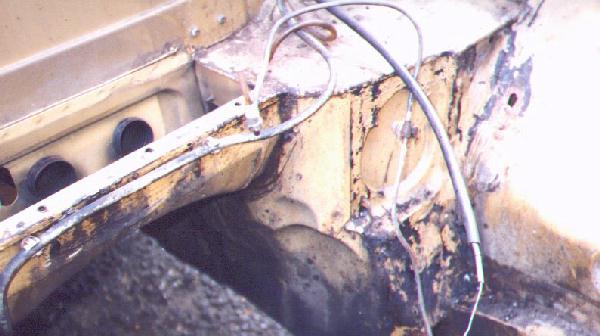
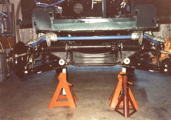
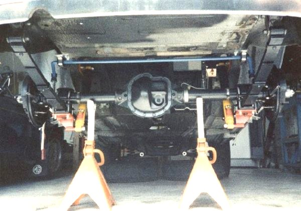
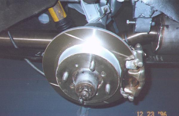
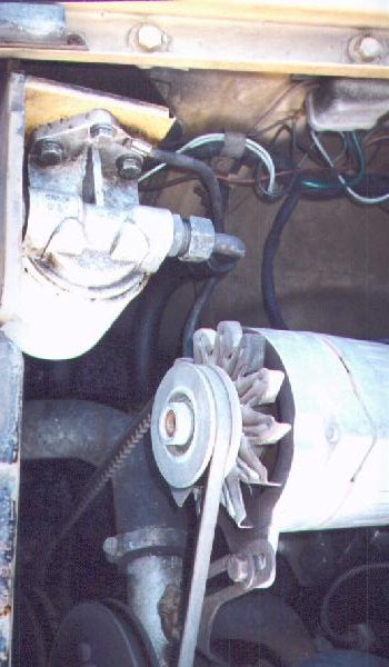
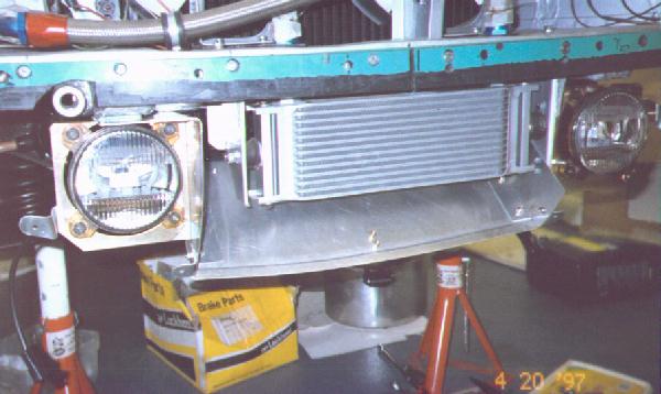
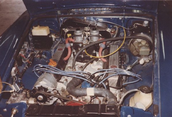
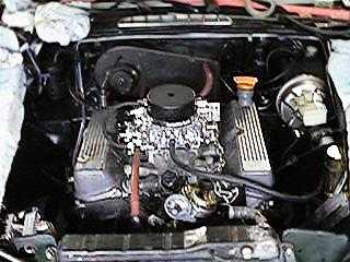
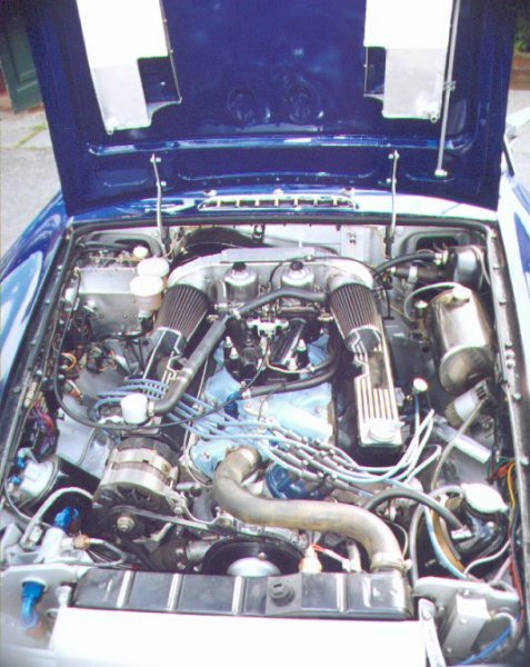
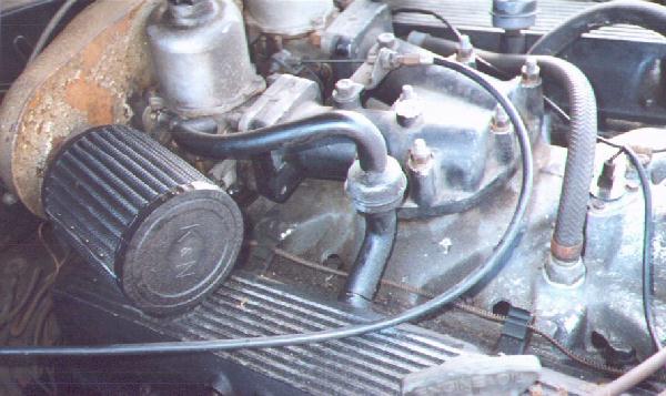
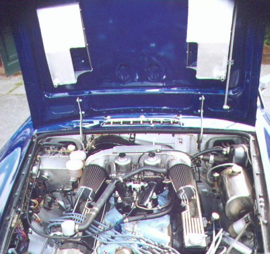
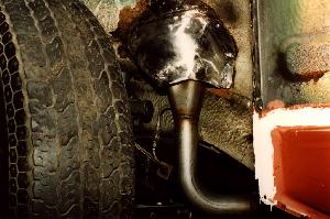
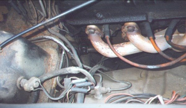
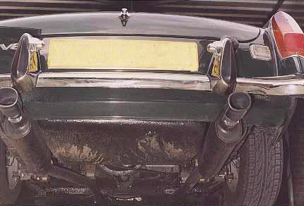