|
|
|
|
|
|
|
|
|
|
|
|
|
|
|
|
|
End of Menu Items |


XPAG Oil leaks - and cures

This page attempts to pool together all the current documents published on XPAG oil leaks. It is not exhaustive by any means, and all opinions offered are those of the authors of the articlesand do not necessarily reflect those of the MG Car Club Y Type Register. Please also see our Disclaimer page. All prices quoted as of the time the original articles were first published: they may now be different. Although written primarily for the T Register (Dave DuBois is an active member of the North American Northwest MG T Register), the articles are just as applicable to any XPAG or XPEG engine.
How to Stop (Almost All) Oil Leaks in Your T-Car The Cheap and Easy Way |
||
Rear Engine Oil Seal (Otherwise known as "If it works, leave it alone") | ||
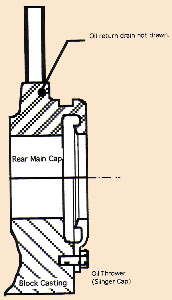 The rear main bearing and bearing cap, showing the "seal" area (the picture is drawn upside down). |
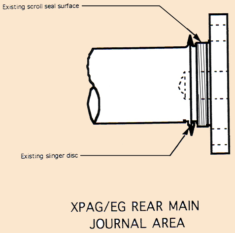 The oil slinger and the scroll surface at the rear of the crankshaft. |
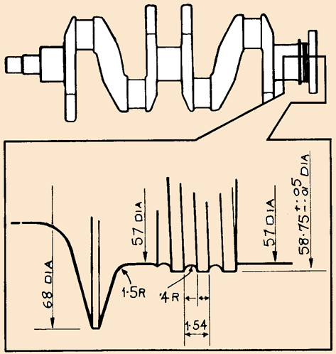 An expanded view of the scroll threads, with dimensions (see the article titled "Archimedes - Type Rear Crankshaft Seals" by Chris Nowlan). |
![]()

Causes of Oil Leaks in XPAG-XPEG engine
by Dave DuBois
I have attached a number of articles regarding the rear main seal. There is some information on the Moss seal and on the Bradley seal, which are two different attempts to install modern lip seals to the rear main bearing. Both of these modifications require a certain amount of machine work be done to the engine and there is no guarantee that either will work properly. Both seem to work sometimes but not always. I'm not sure that either even hits the .500 mark. There are also articles by Chris Nowlan, John Seim and Skip Barns with three different looks at controlling leaks. The pictures that I have attached and the description and picture in Chris Nowlan's article will give you a good idea of how the rear main seal is constructed and why it is problematic. My approach on our TD (which never did leak excessively) was a combination of Chris Nowlan's and Skip Burns' approach. When I threw a rod in our engine, I had to get the block welded and also line bored. Line boring the block caused the scroll portion of the crankshaft to rub on the seal surface of the rear main bearing cap, so I worked the seal surface down with a scraper, then fitted the upper seal cap and did the same thing with it. This left the seal surfaces with less than 0.001 clearance from the scroll surface of the crankshaft. I also paid meticulous attention to fitting the gaskets when installing the sump as Skip Burns suggests. When we first got the TD back in 1974, all of the technical experts really emphasized the importance of getting the gaskets properly sealed around the rear main bearing as the secret to minimizing oil leaks. Nobody pays any attention to that since the Moss seal modification came out. It is my guess that a majority of the oil leaks after installing the Moss or Bradley seals are attributable to lack of attention to those gasket ends that we used to pay so much attention to.
You will see from Chris Nowlan's article that the rear main seal is not true seal as with modern lip seals. It is, rather an oil slinger that is cast into the crankshaft and rides in a grove in the rear main bearing cap that leads down into a catch trough and a drain tube that extends down into the oil in the sump. There is a spiral grove just behind the slinger that acts like an Archimedes screw to carry any oil that gets past the slinger back to the drain grove. In theory the only oil that will escape is what little bit is left on the groves when the engine stops. On our car, and on a majority of cars, this works quite well, but it sometimes fail and when it does, it is a real puzzle to cure. Some of the things that can cause it to fail is excessive clearance in the rear main bearing, causing a flood of oil that overpowers the slinger and threads. Excessive, or uneven clearance of the seal surface around the spiral grove will also cause excessive leakage, as will excessive crankcase pressure. Excessive crankcase pressure can be caused by the tappet cover gasket collapsing against the inside of the cover, blocking the breather pipe or by worn compression rings or worn cylinder walls
Some people have removed or cut off the pipe that extends from the oil trough in the rear main bearing cap in an attempt to cure the leak at the rear. The rational for this is that the early B series engines used in the MGAs and early MGBs have the same rear main seal arrangement sans the pipe that extends down into the oil in the sump. Others have drilled additional drain holes into the trough to provide more drain capability. I disagree with the assertion that this pipe will siphon the oil out of the sump when the engine is shut off, as that is not how a siphon works, as the output end of a siphon has to be below the level of the fluid it is siphoning. While I can understand how a possible air lock can develop in the pipe extending down into the oil, my thoughts is that if the drain is being overpowered by the volume of oil, then the rear main bearing clearance is probably excessive. Regardless of the physics of this arrangement, it probably doesn't hurt anything to cut the pipe shorter.
At this point, let me go over some of the many places that the XPAG/XPEG engines can and do leak. Starting at the top, the rocker cover is a notorious leaker. This can usually be eliminated by gluing the gasket to the head with a hardening gasket sealer such as Permatex 97B and insuring that the sealing surface of the rocker cover is flat and true. I have trued the cover on our TD with sand paper on my table saw table. Next is the tappet cover gasket. Some people use two gaskets here to try to stop leaks. My experience is that often the head gasket extensions that go to the left side of the engine extend a bit past the edge of the head and block and cut into the gasket. I now check that area and file off the protruding gasket flush with the side of the engine. Again, I glue it all together with Permatex 97B. Another place for an oil leak is from the head gasket itself. This is more likely due to an imperfect finish on the head or block surfaces rather than the gasket itself. There is also a pipe that bring oil up from the gallery in the block to the head. This pipe is attached at both ends with banjo fittings that have a copper crush washer on both sides of the fittings. If the washers are reused, they can start leaking. Going forward, the oil pump can be a source of leakage as can the front crankshaft seal (more on this seal later). A distributor with worn bushings can fill up with oil and dribble down the side of the engine for another leak. The one thing common to all of these leaks is that they all run down the side of the engine and get blown along the sump to the back and when the car is stopped, the oil drips off of the flywheel housing, which also contains the drain hole to shed any oil leaked from the rear main seal, making it look like the rear main seal is leaking. This reminds me of another potential source of an oil leak, and one that will definitely cause oil to come out of the drain hole. There is a welch plug at the rear end of the camshaft and if it leaks, the oil goes down the back of the engine and out the drain hole.
Before doing anything in the way of leak suppression, I would suggest either have the engine steam cleaned or get several cans of Gunk engine cleaner and completely clean the exterior of the engine. After doing that get some leak detect dye to put in the oil and a black light. Go out and run the car for a good long run, then take it back into the garage and start using the black light to find any oil leaks. With the limited access in the engine compartment of the TF you are probably going to need a good inspection mirror to do this and it may take several runs to find everything. I don't know how difficult it is to remove the side panels from the engine compartment of the TF, but that is also an option while you are hunting down leaks.
The leak indication on the front of the timing cover could be from a leaky rocker cover along the front edge, but most likely it is the front seal or a crack in the crankshaft pulley. The front seal is the old rope seal (graphite impregnated rope) and it rides on an extension from the back of the crankshaft pulley. You can check the pulley extension by removing the pulley (you may have to lift the front of the engine to clear the front cross member) and inspecting the extension along the line of the keyway, which is where they always crack. I don't think that the crack leaks so much oil as it shaves the seal away and allows the oil to go past it. I have including a list of modern lip seals that can be used to replace the rope seal at the front, but it requires removal of the timing chain cove at a minimum and preferably removal of the sump. Even then, it is a bit fiddly to get this seal installed properly because you are trying to fit it into a grove meant for the rope seal and requires some judicious use of RTV type of sealant (the only place other than the ends of the sump gasket where RTV sealant is appropriate in my opinion).
Regarding tolerating oil leaks, one thing that helps is to get one of the large drip pans and line the inside with one of the drip carpets. The drip carpet is very dark in color so you can't see any of the drips that hit it (kind of like a little kid wetting is pants while wearing dark pants). With this approach, you just have to be sure that you never park the car on a light concrete surface at home. You can also stop thinking of them as leaks, bur rather as an automatic rust proofing system for the underside of the car. When our car wore out the cylinders, I was getting so much blow by that most of the oil was being blown out of the breather pipe that it completely coated the underside of the car and frame. Parking the car in the garage after driving it very far, resulted in an oily outline of the frame on the concrete floor — That's excessive!
I hope that all of this helps somewhat.
![]()
How to Stop (Almost All) Oil Leaks in Your T-Car The Cheap and Easy Way
by Skip Burns
After thirty years of fiddling with XPAG engines, I've long held the notion that the majority of oil leaks are caused by improper installation of the cork seal on the rear bearing cap. The result has been more articles about how to fix oil leaks in T-Series cars than on any other subject. Nearly all have recommended installing "other car" seals, not to mention the well-known Moss crank seal. In many cases, this means yanking the engine out of the car, extensive machine work and money. Lots of it.
I've seen some real leakers in my time, including my own car (TB). Some owners have gone so far as to install little reservoirs under the sump in an effort to stop oil from dribbling onto the garage floor. I know one guy who even tried to figure out a way to get this oil back into the engine...automatically. He failed, of course.
We know that with the initial production run of the TC, Abingdon was picking bits and pieces out of the dustbin as the cars came down the line. Money was tight, as were top grade materials. Nevertheless, one still reads bulletin board messages from owners trying in vain to obtain "original" parts — like nuts and bolts for the frame — and "original" paint colours, when few realize that for a couple of extra pounds, Abingdon would paint polka dots on your car. Still, I got to thinking — would Abingdon knowingly produce a car that dropped oil by the quart? Hark, is that a tumultuous, resounding "YES!" I hear in the background. I don't think so.
What we have is an older car fitted with anachronistic seals. The asbestos rope seal on the crank pulley is a prime example of steam engine technology. Today, there is a replacement...the lip seal. The cork seal at the rear is another anachronism, but with care, it will work pretty well. Honest! The secret lies in prepping the seals correctly before installation and then putting everything back together precisely in the proper sequence, plus purchasing a few inexpensive items from your local auto store. Will it still leak? Maybe."maybe not. It depends on how careful you are and if you have the patience to do it right the first time. Doing it right requires thoughtfulness — and precise timing. If you do this right, at least your car won't be dropping large quantities of oil on your pristine garage floor.
Start by ordering up some inexpensive parts. Using the Moss catalogue as a reference, order two oil pan gaskets (part no. 291-000). Why two? You're probably going to botch the first one; the standby will be your backup. At the same time, order the one-piece lip seal (part no. 120-750) that's going to replace the rope seal. You'll also need to order a timing chain cover seal (part no. 291-600), because you're going to be pulling the cover in order to properly install the lip seal. TB owners will need to buy some gasket material to hand-make a gasket, because no one makes TB timing chain cover gaskets any more. Next, go down to your local auto supply house and purchase one tube of silicone sealant (Permatex Blue RTV with the code 6B on the bottom) and a small can of Permatex High Tack Spray-a-Gasket Sealant (comes is a blue can and may have the name Loctite on it). Why High Tack Spray? Because using silicone sealer with abandon in the wrong places can ruin your day. If you apply it to the sump gasket and use too much, it may squeeze out and drop into the oil pan where it can find its way into the oil galleries. Ouch! Moreover, the next time you try to remove the sump, you may need a jackhammer to get it off. A final word, you're going to be removing a lot of bolts. Inspect each carefully for stretching or corrosion before reinstalling and replace as needed.
As the saying goes, "tidy ship, tidy mind." Clear a bench or table where you can temporarily store bits and pieces removed from the engine. Timing is going to play a role and you don't want to lose time rummaging through a pile of stuff looking for a part you took off two days ago.
Start by clearing the decks. Remove the radiator shell and radiator. Check the hoses and while you're at it and consider replacing them. Pull the fan, the timing chain cover and drop the sump. Loosen the bolt holding the crank pulley and remove it. This might be a good time to clean up and put a dab of paint on the TDC mark — maybe even adding the 5 and 10 degree advance marks mentioned in Part I of "How to do a Complete Engine Tune-up". Remove the old cork seal attached to the bearing cap. Clean (scrape) all sealing surfaces — sump, bearing cap, block, and timing chain cover — scrupulously.
Next, place the sump on a bench and lay the raw gaskets in place. It helps to drop some bolts in to keep them from sliding around. Formerly, the front end of the gasket extended between the ends of the rope seal and was crushed by it, making a tight seal. Okay, maybe not that tight! With the new lip seal in place, you can easily see that the end of the gasket is going to interfere. Using a ball peen hammer and holding the gasket firmly in place with the holes lined up, carefully tap, tap, and tap the gasket where the lip seal slot is. This will indent the underside and show you where to remove a tiny portion of the gasket. If you really want to get a good seal, take care when cutting the gasket. You'll want those two little tab ends of the gasket to remain so they will cover both sides of the lip seal. I used a sharp pair of scissors and was lucky enough to remove just the right amount of gasket material. So can you, provided your patient and work slowly.
Take the timing chain cover and clean out the slot where the lip seal is going to be inserted. When you certain it's clean, apply a small amount of silicone sealer — not too much because you don't want any spilling out the sides of the slot. Insert the seal and press fit it into the slot. Make sure the flat side of the seal is facing forward and the slotted side with the spring in it is facing toward the engine. It should be a firm fit. Wipe off any excess silicone and quit for the day. Allow 24 hours for the silicone to cure and glue the seal to the cover.
Next day is Hallelujah Day. Inspect the lip seal and make sure it's firmly adhered to the slot. Don't pull on it or try to rotate it, you may dislodge it causing you to start over. Apply a dollop of grease to the inner surface of the seal. This will prevent it being burnished when the engine is first started and before oil pressure is attained. Assuming you're satisfied, lay out several layers of newspaper on a flat surface and spray the timing chain gasket with the high tack sealer...both sides. Soak it. Insert the bolts into the cover and place the gasket on the cover so that the bolts hold it in place while you manoeuvre the cover into position. Using care, place the timing chain cover up close to the bearing plate. Then manoeuvre the cover so as to slip the lip seal over the end of the crank. Install and tighten the bolts that attach the cover to the front bearing plate.
The order and timing for installing the sump with its gasket and the cork gasket are critical. Look at the sump gasket and note that the zig-zagged ends adjacent to the cork gasket hang over the edge of the sump. This is important. As already stated, it's long been my belief that the majority of big oil leaks occur at this point because these two gaskets are installed out of order, crushing the ends of the sump gasket, thereby allowing oil to escape around the ends. If the gasket ends don't butt up against the cork gasket, a major leak is forecast. This means the sump gasket must be installed before the cork gasket.
The cork gasket itself can be installed improperly. The partial cuts at the ends of the gasket are supposed to slip into the slotted openings in the bearing cap, but not all the way. When the sump is installed and the bolts tightened, it squeezes the gasket and pushes the ends all the way up into the bearing cap, but not before. I have botched the job at earlier times by inserting the cork gasket all the way up into the slot on one side, leaving the other side too short to be squeezed up into its receptacle. In this instance, that the cork gasket appears to be okay is an illusion because the sides of the slot hold it in place. To preclude this from happening to you, mark the absolute centre of the bottom of the cork gasket with a pen. Later, when inserting this gasket, check to make sure the gasket is centred by checking the mark at bottom dead centre of the slot.
With the cork gasket marked but not installed, it's time to install the sump gaskets. Again, lay out some newspapers and apply a liberal dose of high-tack sealer to only one side — the side that butts up against the block. Leave the other side clean. Apply the gaskets to the block. The high-tack sealer should hold them there. If it doesn't, pull them off and give them another dose of sealant. Eventually, they'll stick. With the sump gasket sticking to the block, insert the cork gasket into the slot on the bearing cap. Check your mark to make sure it's centred. The sides of the slot should hold it there provided you've pressed the cork well into the slot. The jagged ends of the sump gasket should now just be nudging the cork seal. By the way, I wore surgical gloves while messing with the high-tack gasket sealer.
With both gaskets in place, grab the can of high-tack and spray the underside of the sump gasket...liberally. Some haste is required as you don't want to let the upper side of the sump gasket to dry out. Now, you're ready to reinstall the sump itself. When that's done, you're almost through. Don't forget to apply a dab of silicone sealer in the slot at the front of the sump where the lip seal will sit. With the sump in place, the crank pulley should slide right through the lip seal ready to be tightened down. Remember the washer that goes between the nut and the pulley. Reinstall the radiator, shell and connect the hoses and you're done. Don't forget the bolts that attach the sump to the transmission housing.
One additional note on oil leaks. Never, never remove the banjo bolts that connect the oil lines to the filter and block without replacing the copper washers that go on both sides of the banjos. In tightening these bolts, old copper washers can shred bits of copper off and cause leaks.
I highly recommend warming up the engine two or three times and checking for leaks before hitting the road. Run it up and let it cool down, all the time checking for the odd leak. It's almost certain that you'll find several timing chain and/or sump bolts needing an extra turn.
I made all the foregoing mods to Abbie. No oil leaks up front. Maybe a tiny drop at the rear after a very long, hard run — if that much. As my granddaughters like to say, "That's cool, Bop Bop." Hallelujah!
![]()
Archimedes - Type Rear Crankshaft Seals
by Chris Nowlan
Perhaps the most annoying source of oil leaks in older British sports car engines is the mechanical oil slinger/seal arrangement designed as the primary rear crankshaft seal. The theory of this Archimedes-principle seal, is that the spiral grooves at the back of the crank fit with only a slight clearance to the stationary upper and lower oil control surfaces. As the crankshaft rotates, the action of the reverse oil control threads against the flat sealing surfaces draws the excess oil back into the hollow cavity next to the rear bearing where the oil drains harmlessly back to the oil pan.
In reality, this seal arrangement works well as long as minimum clearances are maintained. A slight amount of leakage is inevitable when the engine is shut down. This residual oil drains through a small hole in the bell housing and should not amount to more than a few drops escaping on to your driveway
Since the oil control threads and the sealing surface are not supposed to wear, few workshop manuals offer detailed instructions on the fitting of these seals nor quote specific clearances. In studying engineering drawings for the T-series crankshaft and rear main upper seal, factory clearances can be calculated to 0.0053" minimum to 0.0088" maximum. The MGA Workshop Manual specifies a total clearance of 0.003" to 0.006". Although the T-series spec. seems overly generous, the MGA spec. appears more reasonable and can be considered a guide for all applications.
An expanded view of the scroll threads, with dimensions.
Since the oil control threads and the sealing surface are not supposed to wear, few workshop manuals offer detailed instructions on the fitting of these seals nor quote specific clearances. In studying engineering drawings for the T-series crankshaft and rear main upper seal, factory clearances can be calculated to 0.0053" minimum to 0.0088" maximum. The MGA Workshop Manual specifies a total clearance of 0.003" to 0.006". Although the T-series spec. seems overly generous, the MGA spec. appears more reasonable and can be considered a guide for all applications.
The sealing surfaces (and, to a lesser extent, the oil control threads) will wear if the rear main bearings become excessively worn or if the block alignment becomes distorted. Leakage problems can also result from inaccurately refitting the replaceable sealing surfaces used on many British sports cars. Jaguar and TR2-4A used replaceable upper and lower seals, Austin-Healey 100-4 and MG TC-TD-TF used only a replaceable upper seal while the MGA and 6 cylinder Healey incorporated sealing surfaces cast integrally with both the block and rear main cap.
In renewing this critical seal, a number of alternative techniques can be employed. Perhaps the most foolproof and effective method is to have your block and the sealing surfaces line-bored by a competent machine shop. By carefully measuring bearing saddle dimensions and/or the diameter of the oil control threads, correct oil seal diameters can be determined. This is a fairly expensive operation but is the only way to restore non-replaceable sealing surfaces. (MGA owners take note, as this is a common problem!)
Replaceable seals can be hand-fitted with care and considerable patience. The crankshaft and main bearings should first be installed and checked for proper clearance using "Plastigauge", available from any automotive machine shop. Also, check to be certain the crank rotates freely and has proper end float, then remove crank and prepare to trial fit bolt-on sealing plates. On MG TC-TD-TF blocks, remove the two small dowel pins, as these would effectively prevent any adjustment in the location of the seal. Install seal loosely, using appropriate gasket and gasket cement. Apply a thin film of engineer's bluing (the thicker type sold in squeeze tubes is easier to work with) to the sealing face. With the seal fixing bolts slightly loose it should be possible to snug and center the seal against the crank. After tightening up the seal, torque the lubricated crank assembly to full spec. Now, carefully rotate the crank once or twice before removing the crank once again to inspect the contact pattern on the seal. The ideal situation is to adjust the seal so that you are left with a very thin film of engineer's bluing on the sealing surfaces. Particular attention should be paid to the upper sealing surface on the block as these are most subject to wear and are consequently most critical.
In some cases, it may be necessary to remove some material from the parting face of one or both seals. This must be done carefully; lay sandpaper on a dead flat surface or pane of glass to help insure accuracy. It maybe necessary to remove and refit the crank five to six times to insure that you have achieved a correct fit. A certain degree of light contact is not generally objectionable, particularly with the replaceable aluminum seals, as these will bed-in as soon as the engine is started. Heavy contact that makes the crank difficult to rotate could, however, cause serious problems. The small dowel pins originally used with the T-series seals are not really required and their reinstallation can cause distortion and/or a shift in location of the plate. If these pins are reinstalled, recheck your work once again.
Once the seals have been installed, checked and rechecked, assembly can continue but may require that the crank be removed once again in order to install connecting rods and pistons (Remember folks, patience is the ultimate virtue!). Last, but not least, particular care should be exercised in installing the oil pan together with all appropriate gaskets and seals (See How to Stop (Almost All) Oil Leaks in Your T-Car The Cheap and Easy Way by Skip Burns above).
Having hand fitted and determined with all certainty that you have achieved a correct fit, your rear main seal should be nearly 100% drip free. A last word of advice: be sure that your crankcase breathers are clean and free of obstruction and that your gearbox first motion shaft seal is in good order. A problem in either can otherwise mask over a job well done.
![]()
Engine Oil Seal
by G M by Andrew Bradley
The "Moss kit" SOMETIMES works. I know many people who have had great successes with them and consider them the best thing since sliced bread. I also know many people who have poured countless hours and quite a few dollars trying to get the Moss kit to work, the results still being toasted seals and oil leaks. I went through two Moss seals and an additional Viton seal with no long term success, even though the seals were installed with less than 0.002" of run out and perpendicularity within 0.001", with a micro polished crank flange! The fault is not with the design, or the installation procedure. The problem comes from the seal itself.
The problem is that the seal was not designed for a shaft of not quite 4 inches to be spinning at something around 4000 rpm*. Go down to your local industrial bearing supply house and look at the specifications in the front of a CR or National Seal catalog, do the calculations, and you'll see that such an installation is at the ragged end of acceptable use for those seals. Taking into account the not-so-perfect surface condition of the flange and the non-NASA concentricity of the carrier arrangement, it is no surprise that a large percentage of them cook within 1K miles.
Now the good news. If you are considering installing a Moss kit, you are already looking at pulling the engine out, partially disassembling the little beggar and using up half of a gasket kit. With a bit of disassembly, a trip to your local machine shop, and a $6-$8 part, I can virtually guarantee you won't leak again! The answer comes in the shape of a rear main seal for a small-block Chevy (Gag! Choke!). Fork out the big $2 more for the heavy-duty silicone one. Fel Pro: BS 40013 or equivalent. This is a split seal that even has nifty little ridges that act like the old Archimedes' screw to wipe extra oil away from the sealing lip so that it lasts even longer!
The process is simple. Tear your engine apart (Go ahead. You know you want to...). You can have a good look at your rings and bearings while you're at it. Take the nice clean block, the rear main cap, the top half of that silly slinger arrangement and your crank down to your local machinist. Doesn't have to be an automotive one. It might even be cheaper to go to a good job shop. Bolt up the rear cap and the slinger plate to the block. Make sure that the pins fit well. Have the machinist set the block up on his mill or boring machine, dial it in off of the bearing I.D., and make three cuts (You can get exact dimensions from any shop that does Chevy engines, you can measure a Chevy block, or you can just get the machinist to do the measurements then and there.). You will want to open up the bore of the screw surface to fit the diameter of the groove on the outside of the new seal. Then take two facing cuts, on the front and on the rear of the old slinger to make a flange of the correct width to hold the new seal. That's half the job.
Mount the crank in a lathe or crank grinder, and turn the old scroll surface down. A low penetrating weld bead might be beaded, to build up the LD. surface to that required for the new seal. Final diameter is same as a small-block Chevy. You can even remove that little slinger disc part ahead of the scroll, too. Finish it to a good micro-polish and its done. I don't consider it too blasphemous to cut original parts in this manner. They never really worked anyway...**
Clean the block, gather up a new set of gaskets, bearings, and what have you, and assemble as you would normally, with the following considerations. Don't bother with the paper gasket behind the slinger plate. A thin film of silicone behind it will do the job better. Press half of the seal into the block half of the new, flange before dropping the crank in. Press the other half onto the new flange on the main cap. A dab of silicone between the two surfaces will seal them together, but don't silicone the mating faces of the split seal. It is meant to go together with a bit of a crush.
This may sound like a daunting task, but it sounds much more complicated than it really is. The machine work is extremely straight forward for any competent machine shop, and it should cost about half of what just buying a Moss kit does. You will end up with a modern seal doing exactly what it was designed to do, in the environment in which it was meant to do it. It is also running at a fraction of the surface speed of the Moss arrangement, so wear is hardly an issue.
*The Moss seal is using a different seal now that purports to have corrected this problem, see the article titled " Improved Moss Oil Seals".
**I have to disagree with this statement, as the original system worked relatively well in the cars since 1939 and still works very well in our TD - Dave DuBois.
![]()
Front Oil Seal Part Numbers
by Dave DuBois
| ID | OD | Width | |
| Volvo cam oil seal P/N 6842273 | |||
| Moss P/N 120-750 | |||
| Chicago Rawhide P/N 13537 | 1.375" | 1.832" | 0.313" |
| or P/N 36x47x7 | 36mm | 47mm | 7mm |
If the portion of the crankshaft pulley where the seal rides is worn, Chicago Rawhide supplies a product known as a Speedi-Sleeve, P/N 99138 that can be fitted to the pulley to make the seal fit correctly.
Note: the Chicago Rawhide P/Ns may be prefixed with CR.
![]()
Improved Moss Oil Seals
A message to T-Series (and Y) owners everywhere:
It has been over seven years since I first started manufacturing and selling the Moss Oil Seal Kit and total sales are rapidly approaching 2000. True, there have been some problems and some articles have appeared worldwide "bad mouthing" my Kit.
The "problems" stem from three sources:
- We are working in an area of the engine that was not designed with any precision or consistency by the factory.
- Many "mechanics" refuse to carefully read and follow the instructions provided with the kit, and finally.
- The seal provided in the Kit (Chicago Rawhide #37388) was not designed for the RPM and temperatures encountered in some T-Series engines. This notwithstanding, they do work, even in racing engines.
One of the many advantages of my Kit is that no modifications to the major engine components are required, unlike the very major modifications required by other installations, many of which still leak!
I am proud and happy to announce that I have been working with Chicago Rawhide since last year and we have come up with a new and vastly improved oil seal to replace the 37388. While the dimensions of this new seal are the same; the improvements are:
- The seal is made of graphite impregnated Teflon, the finest seal material known.
- The seal is rated to 12,000 RPM, a figure reached by very few T-Series engines.
- The seal is rated to 600 degrees F.
- The lip of the seal has been moved back to insure better contact on the surface of the crankshaft flange, and,
- The lip of the seal has a reverse spiral to control the flow of oil.
All Kits supplied henceforth will include this new seal. I can supply this new seal for $26.00 (price correct at time of printing) ppd.
Al Moss
Now c/o Moss Motors USA and Europe
![]()
Rear Engine Oil Seal (Otherwise known as "If it
works, leave it alone")
by John Seim
Recalling those words of wisdom, I took a hard look at both the Moss Oil Seal, and the GM rear oil seal. I looked at the MG engine block, and wondered, "Why would MG (Morris) put a seal in the back of the engine that didn't work?". Then it came to me. Morris put a rear oil seal (Thrower Plate) in the back of the engine. This design dates back to the mid-thirties, but probably was part of the Continental engine design, when the engine was initially designed, in the late tens. It worked well at that time (the tens), it just wasn't state of the art in the post-war years.
What they incorporated in their design, was an Archimedes screw to return the oil back into the block, that had worked it's way to the rear-most portion of the crankshaft. The Archimedes screw is at the back of the crankshaft, then an oil barrier (plate), then the large flange for the flywheel mounting. In the engine block, at the back of the rear main bearing cap, was a flange lip that would surround one half of the Archimedes screw. The thrower plate mounts directly to the rear of the block. It supplies the other half to surround the Archimedes screw. The thrower plate butts up to the bottom of the rear main bearing cap, and is secured by two pins and by three 6mm x 1.0 bolts. The design worked reasonably well, as long as the clearance between the Archimedes screw and the rear main bearing cap/ thrower plate was kept to a minimum.
What happens is that the crankshaft flexes. Remember, these weren't balanced crankshafts, or flywheels, or other moving parts. A small amount of unbalanced weight, over the years, moves the part in an elliptic, rather than a circular motion. Add the weight of the flywheel attached to the rear of the crankshaft, and you can either increase the unbalanced weight ( if both unbalanced weights are placed on the same side) or move the imbalance by installing the flywheel having a greater imbalance that that existing in the crankshaft, to the opposite side of the crankshaft's imbalance. In any event, the wear at the rear main bearing is greater than either the centre or front main bearings. This wear allows for the Archimedes screw to move outward into the circular surfaces of the rear main bearing cap/thrower plate, enlarging the opening. With a larger opening (clearance), the Archimedes screw becomes inefficient. No where in the workshop manuals does it mention to check clearance at this point. Jim Bigler, Jerry Felper, and others knew that the thrower plate had to be butted against the rear main bearing cap. In fact, they would advocate removing the two pins, and tap the thrower plate up against the rear main bearing cap, with the cap torqued to spec to the engine block. Bud Quist took this one step farther. So, what's the solution?
- Have all parts of the engine balanced. Then, mount the rear main bearing cap to the block, torqueing the nuts to spec. Install the thrower plate, using the three bolts and the two pins (I would remove and discard the pins. D. DuBois), plus the gasket, and gasket cement. Do not tighten snug the bolts. Tap the thrower plate at the left and right pin corners, to butt the plate to the rear main cap. This also bends the pins, helping to keep the plate against the rear main cap. With this completed, now tighten the three bolts snug.
- Smear a thin coat of J-B weld on both of the semi-circular surfaces.
- Install new main bearings into the engine and main bearing caps.
- Using Teflon tape, wrap two turns around the Archimedes screw portion of the crankshaft. Press the tape into the screw threads. The Teflon tape acts as a release agent, and helps to remove the J-B weld from the screw threads.
- Lay the crankshaft in the block.
- Install and tighten to spec the centre and rear main bearing cap.
- Rotate the crankshaft in the direction that it spins, two or three complete revolutions.
- Remove the centre and rear main bearing cap.
- Remove the crankshaft. Pull the Teflon tape out of the threads. Use a dental pick, or other tools, and remove any remaining J-B weld residue.
- Remove any excess J-B weld in the rear main bearing cap, oil thrower, or engine, not on the circular surfaces.
- Let J-B weld sit for 24 hours.
- Repeat steps 4-10.
This completes the repair of the circular surfaces. The Archimedes screw now has a minimum clearance to work with. When assembling the engine, place some gasket cement on the flat surface of the oil thrower. This seals the circular area. Almost all oil will now be returned to the engine. You will have a small leak, better than when the engine was new. The cost of this repair is about $5.00.
![]()