If you have any handy hints or tips you'd like to share with other Y owners, please contact either of our Technobods (Tony Slattery and Paul Barrow) us via our Contact Us page and supply details of the your suggestion and we will contact you for pictures or more details.
You should hopefully receive a reply within a few days.
Clean off road dirt and any underseal from the top of the damper.
Remove the filler plug from the top of the damper (original fittings are 1/4” Whitworth heads – webmaster comment).
A cotton bud makes an excellent dipstick. (Consider removing the cotton wool from the cotton bud so it does not contaminate oil in the damper – webmaster comment).
Check the hydraulic oil level in the damper housings using the cleaned off cotton bud stick.
If necessary, using a syringe, to top up the oil to the bottom of the filler plug hole.
Wrap tissue paper/absorbent kitchen roll around the locations where the shafts protrude, the damper housing and around the threaded end caps and secure with cable tie.
Take the car on a half an hour ride on some bumpy roads.
Remove the cable strips and paper wrappings and check if any of the paper straps are wet.
The Y-Type was never fitted with a coolant temperature gauge from the factory. I have seen many “aftermarket” gauges fitted with temperature senders in various locations – radiator top tank – bypass outlet from thermostat – bypass hose itself – and even in the elbow directly under the thermostat (ideal location).
I have myself run electrical aftermarket gauges with the sender under the thermostat, and found them to be pretty good if you can keep an eye on the gauge, but they are difficult to calibrate and be sure they are giving good readings. I once had a sudden loss of coolant due to a dislodged expansion plug, and if it wasn’t for a whiff of “hot water smell” the engine would have been cooked – the gauge read normal despite the loss of coolant.
I now prefer to install an “Engine Guard” – https://engineguard.com.au/. I am sure there are other brands on the market around the world, but for me in Australia, "Oz Made is best".
These offer a digital readout and measure the external temperature of the cylinder head, so are not dependant on coolant temperature/presence.
I mounted the sensor on the bottom bolt of the head outlet and fed the wire through a tube along the side of the rocker box using those spare bolts found on export cars we have here in Australia.
Display panel under the dash on a hinged panel to lift it out of sight for the car show purists. In urban areas the temp is around 60 degrees Celcius (140 degrees Fahrenheit) on the outside of the head. This rises to 66 degrees Celcius (150 degrees Fahrenheit) at 100km/h (60 mph), 67 Celcius (153 degrees Fahrenheit) at 105km/h (65 mph) and 68 degrees Celcius (154 degrees Fahrenheit) at 110km/h (68 mph) (measured on relatively flat motorway with ambient outside more than 30 degrees Celcius (86 degrees Fahrenheit) in South-East Queensland). It's brilliant tool that allows you to monitor just how hard you can push the engine and not stress it too much.
It's super accurate - I have the audio alarm set at 90 degrees, but it could be set much lower for additional protection. With the audio alarm you don’t have to watch the gauge and it can be completely “out of sight” if you wish once setup.
They are available directly via the website (see above). I now have four cars fitted with an “Engine Guard” - two classics & two moderns. In time, every car I own will have one - cheap protection.
Tony Slattery, Australia
Overhauling the Front Suspension
Back in 1992 Y Type owner and editor of Practical Classics magazine Brian Cox wrote an article on the overhaul and maintenence of the front suspension on MG Y Types and similar cars and you can download a PDF of here here.
When I bought my YT, nearly 40 years back, it came without a rear seat squab. Some years later and by chance, I discovered the metal part of a YT squab at an upholsterer near where I live (it was just about ready to be upholstered).
The man was kind enough to lend me the squab for two weeks, in order for me to rig up a wooden jig and find the appropriate material(s). He also sold me a couple of lengths of edge-wire that is needed to construct the main body.
For spring samples, I was lucky that a MG mate of mine had a surplus squab of a YA, which he let me have. Unfortunately, on close inspection it showed that the Y springs were longer than a YT’s.
Sadly most of the springs were too rusty to be used (apparently springs get their strengths from the wire-surface of the coils and if there is too much surface rust, the tension is lost).
In search for replacements, I stripped an old Triumph squab that I had in my spares shed and got a couple of sound springs to be used. In addition, I found special assembly clips at an upholstery supplies shop, plus the relevant crimping plyers to “join/fasten” all wire pieces.
The shop also was able to supply me with new springs that were a bit too long, but “my upholstery man” eventually compressed them with lengths of string, to make them shorter.
It filled me with pride when the metal part of the squab was ready to go to the upholsterer.
And even more so when I, after all the blood sweat and tears, I saw the finished product.
It was one hell of a job to bend the mild high tensile edge wires by hand. My thumb nails were gone and the finger tips hurt like hell. Only when I brought my “master piece” to the upholsterer, did I find out that there would have been a hand tool available, to bend the tensile edge wires.
The photo collection also incorporates two “rough workshop drawings”, showing the approximate measurements of the rear seat squab. The drawings have been made at a very early stage of “sorting” the squab (before I found the original metal frame of a squab at the upholsterer) and should be verified with an original squab and your own YT rear body section!
Generally said: don’t make the squab too high, in relation to the front seats – it looks a bit funny if the rear passengers sit higher up than the driver.
Anton Piller, Switzerland
Twin Leading Shoe Brake System Conversions
Steve Priston has written two articles that have been published in Totally T Types 2 digital magazine on converting ths Single Leading Shoe brake system to a Twin Leading Shoe brake system. Steve Prisron has kindly consented for these articles to be available here.
Having browsed the Internet and watched various YouTube videos about Altette horn repair, it seemed to me that they are regarded with some trepidation. (YouTube video 1951 Vincent Rapide, Part 38). This is worth watching as it describes visually what I am trying to say in this Altette guide.
I therefore hope that this description of my efforts may help some other enthusiast to pluck up courage and delve into the Altette horn.
I had the beaten up remains of a late Altette Horn HF1234 12 volt horn that I planned to use on my PB, however I understand that this type was fitted to very late TA/TB/TCs – not sure about this detail, but seems possible, so I thought that ‘Totally T-Type 2’ might be interested in my attempts to get this horn working.
Webmaster’s note: The HF1234 was certainly fitted to the TC. All YAs, Y/Ts (except EX(U) models) and YBs up to YB 0459) were fitted with HF1235 701403.
This type of Altette has a cast iron body and is a simplified version of the earlier horns of the same name, shape and style.
After dismantling the horn, I found that the points were not connected correctly i.e. leads broken and the insulated Tufnol terminal plate was cracked, and there was a flat cupped washer with a rubber insert rolling around on the inside of the casting without any apparent use?
The shims were non-existent.
The chrome bezel on my horn was extremely rusty and corroded, so I purchased a new bezel, new fixing bolts, Tufnol terminal plate and a set of shims from ‘Taff The Horn’. After reading through Taff’s website and the paperwork he sent to me with the parts, I realised that what I thought was going to be an easy job might be more difficult.
I decided to retain the rusty bezel and after de-rusting and resurfacing the pitted steel, I painted it chrome colour, just in case that it might be useful in the future (more of which later).
I then downloaded Lucas Equipment Workshop Instructions from the Internet (click here for a copy!)
This has all the technical information that you are likely to need when fixing these horns.
After de-rusting the cast iron body and un-seizing the fixing and adjusting screws on the rear of the body, I was ready to start rebuilding and here begins some of the conundrums. The Lucas Workshop Instructions did not “exactly” identify my particular model, therefore it is important to get to understand the principles of operation and then apply the knowledge to your particular horn.
On this particular Altette there are just 3 screws on the back, 2 small screws are side by side and they secure the points assembly to the base of the cast iron body, and 1 larger screw that “levels” the points (it does not “adjust” the points gap).
The first check I carried out was to establish if the coil was any good by checking its resistance.
Connect your ohmmeter across the terminals and take a reading; according to the Lucas Workshop Instructions, our 12 volt version should read between 0.70 and 0.75 ohms. Assuming all is well, turn your attention to the inside of the horn casing.
The large screw on the reverse controls the “level” of the points, not the adjustment of the points gap; by turning the screw in or out you will see the points assembly tilting left or right, the object is to get them level within the body of the horn. At this point I realised what the cupped washer with the rubber insert was for. It fits on top of the adjusting screw and provides a cushion to prevent the screw damaging the electrical connection (I think that’s correct, otherwise I’m stumped!).
Next job is to clean the points, these are clamped together with their appropriate flat springs. However, you will notice that there is a triangular Tufnol area with 2 tiny brass rivets attached and when this “ear” is pressed down with your finger, the points will be forced open and it’s possible to insert a strip of emery/wet and dry to clean the points.
Do not force the points open with a lever, just use finger pressure. If you break the points it’s game over and you will need new points – if you can find them!
Now it’s time to think of the shims! I did not have a clue as to “how many” I would need, so I opted for 3 thin ones (Taff supplied various thicknesses). Start with say 2 thin ones on the horn body, then fit the diaphragm. If you dismantled your Altette and shims were fitted, start your rebuild using them as they are a good starting point. Make sure you impregnate shims with Vaseline, don’t use gasket cement of any kind.
Bearing in mind how flimsy the shims are, it’s a good idea to use two 3/16 BSF studs screwed into the horn mounting holes on each side of the horn and fit the shims over them, this helps locate the shims and later the diaphragm.
Having fitted the shims fit the armature, this has an aperture on two sides and it’s an easy matter to sit it into the larger magnet core face. Fit the diaphragm, making sum that the diaphragm is the correct way around; my opinion is that the convex side faces outwards i.e. the bulge around the rim of the diaphragm faces outwards (see next pic).
Screw on the large lock nut, ensuring that diaphragm sits on the shallow ledge machined into the armature and fit the fixing bolts around the diaphragm and tighten them and then tighten the large lock nut.
Fit the points pushrod and its locknut into the armature and screw the pushrod in until you feel it “bottom” – do not over tighten. Hopefully you are now ready to make your first attempt to achieve a sound from your Altette.
Make sure that you use a 12v battery for testing and not a battery charger. I used a cheap 12-volt burglar alarm battery, being convenient and lightweight – at my age I find car batteries a bit too heavy for me.
Rig the 12-volt battery with a lead to one of the 2 terminals on your horn. Using the second lead from the battery gently touch the second terminal on the horn, if you do not get a sound do not hold the lead in contact– ‘Taff the Horn’ warns of this, over and over again – as you are likely to melt the points. At this stage they are probably closed i.e. no gap therefore “no sound.”
This is the point at which your patience is demanded, gently turn the screw half a turn and then touch the lead to the horn terminal. If no sound, try another turn and so on, always making sure that you do not touch the terminal for too long.
Assuming the you do not get a sound from the horn, dismantle the whole assembly, then fit an additional shim under the diaphragm and repeat the whole process!
Hopefully, after carrying out this exercise a couple of times i.e. adding shims, suddenly you get a strangled sound from your horn. Perhaps rather weak but nevertheless “a sound”. Now it’s a question of gently screwing the points push rod in or out until a reasonable sound is achieved, not forgetting to adjust the locknut up tight, as the points rod will quickly unscrew when the horn works. This surprised me as the operation of diaphragm is quite violent and unless the locknut is tightened you may lose it.
The points adjuster and locknut have a very fine thread and not easy to reproduce or find.
So, at last “It’s Alive” and now it’s a further exercise in patience. Find your bezel and make sure that it is still “round” and that there is no old paint or rusty bumps on the inside of the rim.
Also, find the orientation that the bezel was fitted; originally the Lucas logo was at the top, however some bezels have lost their surface finish and who knows where the logo was?
I found that my original bezel had been assembled for so long that it had taken its shape from the casting i.e. it fitted beautifully when using the fixing bolts that hold the horn to the bracket, however turning it one sixth and it did not fit!
Once again ‘Taff the Horn’ insists that the fit is close but not binding – remember that the diaphragm should be held firmly and softly by the shims and not clamped by the bezel in any way.
Once you have sorted your bezel it’s time to fit shims i.e. remove all of the perimeter fixing screws and place your chosen number of shims on top of the diaphragm (I ended with 3), fit the bezel and perimeter screws and tighten them carefully.
Go back to your battery rig and touch power to the terminal as before, do not be surprised if you get no response! Revert to the points adjuster and carefully go through the adjusting sequence again, you should soon get your sound back, it might sound puny and weak; it’s up to you to adjust until you get the sound that you think adequate.
Do not expect the mellow tone of the Twin Windtone with its High and Low horns, the sound from the Altette is harsh but insistent.
Assuming that all is well, fit the Tone Disc and the large dome cover nut, making sure that points locking nut is “locked”. Then try the horn again, it may sound fine — but then again it may not, so remove the Tone Disc and play with the adjuster until you can achieve a sound that suits you.
You can see from all of the above that every time that you tighten or fit components the points adjuster is affected i.e. the points have been opened or closed. The correct air gap between the Armature and the Magnet core face is 18 to 20 thou on our 12 volt Altette, but because it’s under the diaphragm it cannot be seen.
The Lucas Workshop instructions explains, how to measure the gap using a dial gauge. I did not want to spend even more time setting up a “rig” with a dial gauge to establish the gap and then find that I had to alter it to get a sound.
‘Taff the Horn’ suggests using an old bezel to avoid damaging your new chromed bezel whilst carrying out adjustments. Bearing in mind the number of times that the perimeter screws are fitted and then removed to fit shims etc that’s not a bad idea. By now, you should have a horn that works!!
I hope that this long explanation of my experiences with the Altette will help someone else to attempt to repair their rusty horn.
Please note that I am not an auto electrician or an expert in any way and also, I have no connection with ‘Taff the Horn’ other than being a satisfied client of his and appreciating his efforts to educate me in the operation of Altettes.
A great explanation of how the XPAG Cooling System flow is cast into the engine block and how it works is provided here courtesy of Gene Gillam and www.mg-tabc.org (also available from the Downloadables side bar on the News page).
An often over looked aspect of rewiring your Y Type is the seemingly simple task of wiring up the toeboard mounted dip switch. There are three screw connector points ... and three wires and nothing is marked up. Seems simple enough - just put one wire on each terminal. Logic would dictate that the main power feed in would be at the top side and then either the dipped beam or full beam wire on the second or third screw contact and that as the switch is a simple push flip between one or the other it will not matter which output is on which connector. Nothing could be more wrong, but happily you proceed thinking logic says "I am OK - it is a logical thought process!". And so you proceed to mount the switch on the toeboard and then bolt the gearbox tunnel in place, fit the carpets and seats and then set about checking that everything works only to find you only have either main beam or dipped beam and not both. What did you do wrong? Well, you followed logic - that is what!. The correct wiring is actually the main power feed connects to the middle terminal and then either the dipped beam or full beam wire on either the second or third remaining screw contacts ... but now to effect this change (unless the engine is not yet installed) will require a complete strip down and reconnection of the wires. How do I know this? I found out the hard way. This picture shows how not to wire the switch up ... and how it should be wired up!
A great PDF on how to set up your windscreen wipers and how they operate on the MG Y and YB can be downloaded here. The article is reproduced here by kind permission from Walter Prechsl and the MG Octagon Car Club.
The combined switch on the MG Y Series Saloons consists of a Bakelite assembly containing the horn push and a clockwork operated ring to operate the trafficators. There are at least two basic types of switch and they a re similar in principle if not in exact detail.
Complete switch assembly with centre horn button and rotating ring for trafficators. To remove assembly from steering column, push column full forward and lock with half butterfly nut. Remove single attachment screw on steering wheel boss. Pull switch assembly off and remove four wires from switch (if necessary, mark wire positions). Prise chrome ring from boss to reveal spring and spacer. Do not attempt to undo brass screws holding horn contacts to boss. Tease top hat shaped spacer out of boss to reveal cheese headed screw.
Turn switch assembly over and remove paxoline circular shape with four screws. I have marked the screws for identification purposes.
Remove centre screw to release contact cam assembly (note spacer under cam).
Clockwork mechanism can be carefully removed to show timer cams and return spring. Spring can be replaced easily but patience is required as it is a bit fiddly!
Two screws connecting the horn contacts to hub. Short brass screw to earth on hub body, long brass screw connects horn pigtail wire to horn power supply using an insulated sleeve and fibre washer with a nut. Access to this nut and bolt is only after clockwork mechanism has been removed.
Clockwork mechanism can be carefully removed to show timer cams and return spring. Spring can be replaced easily but patience is required as it is a bit fiddly!
Further stripping of trafficator assembly shows spokes on moving outer switch and the pegs on the inner fixed hub of switch. ( have marked these with snopake just for reference). These must be lined up correctly or rotary outer part of switch will not move through full range.
My specific focus here is on work I carried out to fit both flashers and LED bulbs to an MG YB but much of this comes out of my previous work to do the same on a TC and a J2 and will be no doubt applicable to many other, if not all, old cars.
Before getting into the details of fitting LED bulbs and indicators to old cars let me outline a few pertinent general considerations which may complicate what at first sight may appear to be a fairly simple process. My intention is not to put people off from treading down this path as I believe that with a little application and a modicum of confidence electrics can be seen to be not the black art that some believe. In order to try to demystify things as much as possible I will try to break things down into what I believe are the issues to be considered to allow individuals to plan their own way through the maze. I also have to point out that what follows contains my considered opinions, though they are backed up by my technical training and a life spent installing, commissioning and repairing systems much more complicated than our cars.
1. Why fit flashers? The standard answer is to bring our cars up to date. The problem is that it is an old car and we like it precisely because it is not up to date. This is not such a strange assertion as it may seem at first sight as some people coming into the old car movement seem unwilling to accept the true nature of the vehicle they are buying. This question is generally, and more relevantly, followed by the assertion that the original setup is "dangerous" as drivers nowadays don't see the semaphores and are thus unaware of our intentions. This is arguably true, as being positioned on the side of the car they are not only out of the sightline of the following driver but do not flash to catch their attention. The flashing problem can be easily overcome by fitting flashing LED festoon bulbs but this would not really address the problem. Inevitably, however, as we tread warily down this path we come to realise that this throws up other considerations and it is those which I will try to address here. For instance, it is the ideal time to consider whether to use LEDs and to ponder the issue of whether to change polarity of the car from positive to negative - but more of these thorny questions later. Whatever route we take it inevitably requires extra wiring to be run and this immediately throws up the tricky problem of originality, but, again, more of this later. If we are fitting a new wiring loom, and considering the age of the car this may be the first and most important decision we make, we will be getting the extra wires we need but we need to be sure that the loom supplier knows our requirements with regard to which wires we need to run, and to where, in order to avoid the suppliers idea of how to implement the modifications being different from our needs. Just accepting the manufacturers "flasher kit add-on" without understanding exactly what we are buying can be problematic. For instance the manufacturer of the particular loom I used had no provision for a “tell tale” light for the indicators which was incorporated in the particular dash switch I used. Thus we need to be sure from the beginning where we are going with this as changes later can be tricky.
2. Why fit LED bulbs? Here I will use the word "bulb" to refer to a device designed to fit a standard (for our cars) BA15 or BA9 socket and consisting of a number of individual LEDs arranged in an array. Of course we could fit flashers without going down the LED route and this would avoid completely the question of polarity but inevitably there are other things to be taken into account. Firstly let me get out of the way some muddled thinking about LEDs. Ask the average old car owner about LED fitment and the old chestnut about them using less current and thus putting less strain on the generator is bound to be the first thing that comes up. Of course both of these things are true but, as in our cars the generator is perfectly capable of providing the power needed in the first place, are totally irrelevant. Even adding an auxiliary socket for a phone charger or a Satnav, or even a heater blower, is not going to strain the original system beyond its capabilities. Some 1930s MGs did have a problem in this area with generators unable to provide the power necessary even for running with all lights on which is why headlamp bulbs in those days were so low rated (and dim!) but by the time our cars came around after the war technology was much better and, besides, how much night driving do we do anyway? Thus as long as you are not going to fit an outrageous sound or light show system we can't use this as an excuse to go down the LED route. So put away all ideas of fitting an alternator, even if disguised as a generator/dynamo - there's no point apart from bragging rights!
So why do we fit LED lights? Quite simply because they are brighter. They also have the great advantage of being smaller, or at least can be made smaller. This is an important consideration if we are to modify the existing lamp bodies to incorporate extra bulbs to avoid the need to fit ugly or non-original additions but some care is required in choosing which bulbs to use from an ever expanding selection. Here it is pertinent to point out that the individual LEDs in such bulbs can be arranged by the manufacturer to cast their light in various directions so we must take that into account when choosing which one to use and how to orient them in the light units. Of course there are firms who will sell you a ready-made solution to these problems in the form of an insert which they claim is simply fit and forget. My experience is that such claims are never born out in practice. A couple of examples may illustrate this point. Leaving aside the cost, a consideration which I find is less and less relevant to the people who are now coming into the old car movement, we are tying ourselves into a product which has no standard covering it. Thus when it goes wrong we will probably be unable to buy an equivalent unit from another supplier or even from the same supplier, assuming they still exist, as they will probably by then be offering a different, no doubt improved, product. Everything fails eventually and the higher the tech the quicker this is liable to happen. Another problem I have found is that some of these units, due to their integrated nature, can feed stray voltage out into the vehicle wiring sometimes causing unwanted bulbs elsewhere on the vehicle to light. Thus your sidelights may come on with your brake lights, albeit at a lower brightness. At the back this may arguably be an advantage but at the front this may not. It can hardly be argued to be dangerous though. This “feature” is due to the nature of such units which rather than having separate "bulbs", say for brake and sidelights, simply bring on the sidelights at one brightness and increase this for the brakes. This may or may not be a problem, depending on the voltage itself and how other bulbs respond but the problem is easily fixed by the addition of extra diodes. I feel this is just too much to ask of a user though, especially when they have paid as much as they have for a unit full of diodes anyway. I therefore find it easier to stick to individual bulbs, albeit in LED form though the need to use these hybrid bulbs at the rear was forced on me by space considerations inside the ST51 bodies.
3. LEDs are polarity sensitive so whether we should we change the car's whole polarity from positive to negative is a pertinent question. Here the motives and attitudes of the people who are now coming into the old car movement often come into play. If the intention is to fit high tech modern systems on the grounds that someday you may need them I refer you to my previous comments about why you bought an old car in the first place. Speaking to people who espouse this course of action I find more muddled thinking which can be summarised as: "negative earth is better". This is offered without any real evidence, which is not surprising because there is none. What there is is some sort of claim about galvanic corrosion which, while it may be a theoretical possibility it is at best marginal and anyway hardly a credible consideration in cars which are so little used, probably never intentionally go out in the rain and are often undersealed up to their windscreens anyway. The choice of negative or positive earth matters nothing to an electron which only responds to a relative polarity difference regardless of which pole is connected to the metalwork of the vehicle. Even the ubiquitous use of negative earth nowadays is little more than a convention which acts as a standard avoiding the necessity to manufacture two different flavours of equipment. Even the problem of fitting modern negative earth parts to a positive earth car is often fairly easily overcome just by supplying it with the polarity it expects. Or to put it another way: just make sure it is insulated from the car metalwork. A wooden dash makes a perfectly satisfactory insulator or you can just mount the addition to a plastic bracket. This is how I have gone about things with my LED light conversions and guess what - they work.
4. How should we approach the question of originality? Ah yes originality! This question has as many answers as people who have an opinion on it. Inevitably the following will have to reflect my opinion though I will attempt to take as objective a view as possible - a vague hope perhaps. For our immediate purposes this will concentrate on where to site additional indicators at the front and back but also consider whether we should do it at all. I fall into the school which is of the opinion that we should make as few changes to the original system as possible in the knowledge that there may have to be a tradeoff between aesthetics and perceived safety. Of course it goes without saying, I hope, that any changes made should be reversible but I also only really consider them if the law requires it and if they can be concealed as much as possible. The reversibility mantra is commonly heard but I do wonder if it is simply trotted out to justify the owners’ intentions, or deflect criticism of their actions. T Type steering boxes and gearboxes fall into this category and don’t let’s talk about seat belts. Whatever the reason it does make reference to what I consider an important point. Many people in our movement refer to this point by considering themselves to be merely the custodians, rather than owners, of the vehicle. The older something becomes the more this matters. Archaeologists and historians will understand this point best. Even the market recognises this with original vehicles, whether in the form of them being largely untouched or sympathetically restored to original configuration, fetching premium prices. Thus when we and our vehicles are younger we may modify them to suit ourselves with the cry "it's mine and I'll do with it what I want" being often heard. As they, and we, age I feel more respect is called for and originality thus becomes more important. Would you put a brake servo on a veteran car? Issues of safety, especially on modern day roads cannot be totally ignored though.
5. Questions of reliability. This may seem a strange one but any changes we make must consider whether we are actually making the car electrics, or indeed other systems, less reliable. This alone is a good reason for avoiding the use of high tech wizardry as the higher the tech the more chance of it failing. This is really stating the obvious as if something is not fitted it cannot fail though this point may not occur to those who fit modern electronics in place of earlier electro-mechanical technology. Some take hi-tech to extremes, however, and I have even heard of an LED unit which has its own software based controller though I am unsure if this is commercially available. This may be an interesting intellectual exercise but I feel it is seriously disrespectful to ageing machinery. Nevertheless there is a belief that by fitting, say, an electronic ignition system, we are improving reliability. This is only true if our view of reliability is reduced to extending the time between failures. There is an alternative way of looking at things, however, which acknowledges that the original system may be more likely to fail earlier than the high tech one but this is only because it contains more user serviceable parts. There are people who when asked on a bulletin board for how to approach the repair of a generator control box will helpfully recommend fitting a solid state insert which, while it may be capable of giving improved regulation - if setup and specified correctly - in reality it replaces a little understood item with one which only the designer really understands. It also ignores the inherent reliability and effectiveness of the original unit thousands of which are still working satisfactorily after all these years. Will the solid state insert last as long? Remember it contains a lot more parts to fail and do you really understand how it works? And, besides, aren’t we trying to avoid turning our pride and joy into a commodity?
In an old car movement which is moving from being populated by people who have dirt under their fingernails to those who have large wallets the understanding of routine service has moved from being something we do to something we pay for. The loss of technical knowledge that accompanies this means that we are prone to believe hi tech is always better. It may last longer but when it fails it is more likely to do so suddenly leaving us stranded and unable to fix something we don't actually understand, whereas the original system would often allow us to limp home rather than have to call the breakdown service. A little knowledge, and routine servicing, is our saviour at times like this.
Having said all this it has to be said that some aspects of old cars reliability can gain by some degree of modification. Here we have to acknowledge that the Y Type has a particular Achilles heel in the self-cancelling mechanism and the slip ring arrangement to enable the horn and indicator wiring to operate as the steering column turns. Such a mechanism can usefully be bypassed by an auxiliary horn and indicator switch mounted on a separate, relatively low tech, panel as I have done which avoids the mechanical problems of the original. More compromise with originality! Please don’t call me a hypocrite.
6. Practical considerations. Firstly I am assuming a willingness to use a hacksaw, file and drill. If you are happy with these tools you should have no problem. At the front of the car not too much compromise has to be made in order to avoid fitting supplementary indicator units which are arguably fairly ugly by design. In addition the original enclosures are at a better height than the rear to stand a chance of being seen by other drivers. I have used here the smaller sized modern LED bulbs now becoming available to fit both indicators and sidelights in the front Lucas 1130 "torpedo" lights though I have had to use the smaller BA 9s fittings to squeeze them in while adding shrink insulation on my later units to avoid them shorting.
Specialists will sell you 1130 inserts with the larger BA15d fitments intended for a single twin filament bulb. These work satisfactorily when used with filament bulbs but have the disadvantage that both clear and amber colours cannot be got within a single bulb without going to LEDs. Although here in the UK clear indicators at the front are, I believe, legal, as are red at the rear, I feel that amber indicators may avoid too much scrutiny by the uninitiated and at least give a nod to the expectations of other road users. My original solution to this on my TC when still using filament bulbs was to use two with BA9s fitments. Using two separate bulbs also avoids the "stray voltage" problem which I came across on my J2 when I fitted LEDs. The use of two bulbs allowed an easy conversion to LEDs as smaller BA9s units became available along with a variety of colours. In my case, having retained positive earth I had to use an insulator between the metal of the mounting with nylon fixing bolts as well as reverse the bulb connections in order to use easily, and cheaply, available negative earth bulbs. Perhaps somebody will start producing these inserts by 3-D printing. Isn’t technology wonderful – sometimes!
At the rear our ST51, or "D" lamps, require a little more ingenuity. When I rebuilt my TC in the early 1990s, before small, coloured and really bright LED bulbs became available, two bulbs per unit, for brake and sidelights, sufficed as I built a relay unit to emulate the later TD and TF system in which the same filament was used for both brakes and indicators. This was achieved by flashing (or occulting) the brake lights when both were in use. In the YB I have used an arguably better (some would say "safer") system by separating the two out. This simplifies things by doing away with the need for the relay unit but does call for yet another bulb to be shoehorned into an enclosure originally designed for only one. In fact I ended up squeezing two twin filament Led units in either side consisting of indicator, brake, side and reversing lights. This has provided two brake lights and two reversing lights unlike the singles of the original cars. With two bulbs in one I have unfortunately had to use positive earth bulbs, although for convenience I have also used an insulating partition similar to the metal original found in some ST51 enclosures, while using the necessary BA15d bulb holders. The “s”&”d” suffixes indicate single or double contacts. This is probably the place to point out that BA15d holders and bulbs come in two types with either equal or offset locating pins. I have used offset pin bulbs which ensure that bulbs are always inserted the same way round. This matches the commonly available bulbs but I could only find equal pin holders requiring a few minutes work with a rat tail file sort out.
This could also be done on T Type with proper indicators working on both sides of the car rather than relying on little understood hand signals or an expensive relay unit. The single, puny lamp of the original has probably, in most if not all cases, also been long replaced by two, though in the case of T Types reversing lamps would not normally be used.
The insert sellers will tell you that red LEDs work better than white behind the red lenses of the original units. I have found that this is true as a white LEDs output is in a different part of the light frequency spectrum from an incandescent bulb and so they may not look quite as red. Indeed I have found some original lenses where both warm and cool white LED bulbs show a slightly more amber colour. This may arguably be a useful effect if used for emulating the modern amber indicators but how well this works is still to be fully evaluated. I therefore decided to use red LEDs for the brake lights and reversing lights in the outer halves of the ST51 units and white LEDs in the inner halves for the Indicators and Sidelights.
By this means I was also able to use white light through a clear side lens for the number plate illumination. This involved some compromise with the revering lamps as it would undoubtedly be better if they were white but I feel red would work well enough especially as there are now two rather than the single of the original car. To use white reversing lights would require a white lens which would not work for the indicators. I decided to use the brighter half of the two bulbs for the brake lights and indicators for safety reasons relegating the reversing lamps and side lights to the less bright half. This is normal practice for the original filament bulbs where side lights are 5w and brake lights and indicators are 21w. The slight difference in colour between the white and red bulbs of the brake and indicators may be an advantage when both are on together but I am making no real claims for this. I could have used the same bulb, in the outer section, for side and brake lights respectively and gained a certain amount of white light for the reversing light in the inner partition from the number plate window but I feel this would be marginal and besides it would require some sort of interconnection between the red sidelight in the outer partition and the white bulb in the inner partition to provide number plate illumination. A couple of diodes would, I am sure, have sufficed for this but I rejected it as just that bit too complex.
The keen eyed among you will notice that I have not addressed the question of using LED bulbs in the headlights. I feel that this is a separate subject which would throw up regulatory questions which I would like to avoid and besides I have no experience of them. Finally may I please put in a plea for the original semaphores? It would be sad to see their idiosyncrasy lost in the name of progress, reliability or safety so I have managed to retain them in working condition even if their need has been bypassed. The smiles on the onlookers’ faces make their refurbishment well worthwhile.
Make sure the mounting panel under the radiator is free to move on the chassis -left and right, forwards and backwards. Sometimes the holes in the panel can "catch" on the holes in the chassis. I put "copper slip" (anti-sieze paste) between the panel & chassis so it moves easy. To access the bolts on the top side of the radiator mounting panel it is recommended that the front scuttle panel first.
Do not connect the top stays on the radiator -leave them off till last.
First get the height of the radiator correct, so the bonnet verticals align with the body at the rear. Packing washers can go under the radiator or the mount panel -if you need more than 1 or 2 mm of packing check the shape of the mount panel is correct -it has a hump in the middle, it's not straight.
Now get the gaps right at the front of the bonnet each side & at the top by twisting & moving the radiator fore & aft. You may find yourself needing to remove some packing washers, but "shit happens".
Once you are happy it's all lined up, you can then fit the top stays back to the firewall & fit the nuts to the radiator mounting & bolt the mount panel to the chassis.
It's quite a process that can take an hour or two, but it is important.
This double-decker work bench enables you to have all the necessary tools at hand without interfering with the actual dash wiring job.
The bench had been designed to assist work on a YT with the steering wheel / steering column not in place yet. For working on cars with the steering wheel in place the height of the legs may need to be changed.
The 4x4 cut-out in the middle of the table top serves to make room for the gear leaver (and a Shorrock boost gauge I have on my car).
Material List, Dashboard-Wiring Work Bench
Plywood,12mm, approx. (1/2”)
1 only top: 920x300mm, approx. (36x12”)
2 only legs: 500x150mm, approx. (20x6”)
2 only feet: 380x80mm, approx. (15x3”)
2 only wood blocks: 75x50x300mm, approx. (3x2x12”)
Anton Piller
Need a print out of these instructions? Click here.
I had to remove the fuel tank in my YT Tourer to get it repaired, flushed, and sealed after it sat for 32 years.
The car was parked for long term storage with a full tank of fuel with stabilizer added. Thirty-two years later the fuel had evaporated completely, and left behind a conglomeration of dried varnish, rust, and who knows what else. It was found later that the internal baffles had broken free and required repair as well.
Safety First
To make a stable platform for tank removal it is imperative to raise the car off the ground to a sufficient height to be able to easy access under the rear of the car. For stability the front of the car should be raised as well. This is fairly easy when done properly and is safe. Anytime you are putting a car in the air pay. Short-cuts can result in injury and even death.
I use a floor jack of sufficient size and lifting capacity to lift the car. The “saddle” of the floor jack can be rotated so that 2 of the four raised edges are lined up forward on the jack. I lift the front of the car first.
Removing the Tank
Lifting the Front of the Car
Place the floor jack under the car at the centre of the front cross member and push it far enough so that the raised edges of the saddle are just past the rear edge of the cross member. Pump the floor jack up so that the saddle just makes contact with the cross member. Once contact is made pull the floor jack so that the edges of the saddle catch on rear edge of the cross member, and feels “locked-in”. Doing this will reduce the chances of slippage considerably. Lift the car as high as you can and place axle stands* under the front suspension spring pans, in such a manner as to provide a stable non-slip footing. Let the car down until the weight is carried by the jack stands and the car is stable.
* The IMGYTR recommends the placement of ramps under the front wheels rather than axle stands.
Lifting the Rear of the Car
I lift the rear of the car with a floor jack. The only thing that I do different is to put a small piece of softwood in the saddle of the jack. This softwood has a 3/4” hole in it to allow the drain plug of the differential to not hit the saddle directly. I do not know if all Y’s have this protruding pipe plug in the drain, but mine does and I thought it better than risk damaging it by the saddle of the jack.
I raised the car to a height to allow me to put a set of ramps under the tires. If ramps are not available, use jack stand under the leaf springs at the axle housing. This has been proven to be a stable location.
Now that the car is raised to a level to get under it the removal process can begin.
Preparing to remove the fuel tank.
Drain the fuel from the tank by removing the drain plug on the bottom of the tank. Make sure you have a large enough container** to capture all the gasoline that is removed from the tank. Store any gasoline in appropriate sealed container. Replace drain plug.
** A full fuel tank is 36 litres (8 Imperial gallons and 9.5 US Gallons). It is easier to use the fuel pump to drain the tank into small cans “under the bonnet”. Disconnect the flex hose to the carburettor from the fuel pump and add a longer hose to put in a 5 litre (1 Imperial Gallon or 1 US Gallon) can. At 5 litres a time you can tip the fuel into others cars/mowers as you go & need too. IMGYTR
To create a good clearance sufficient to remove the fuel tank, it is recommended to remove the exhaust pipe and silencer/muffler assembly. This is easily done on the Y, and should come away in one piece. A new exhaust manifold gasket will be needed on the re-install. This action will give good clearance to drop the tank from between the frame rails.
The part is done through the boot/trunk.
It is advantageous to remove the wood section of the boot/trunk floor. The right hand side comes out first with the removal of the retaining slot head screws and washers. Once the screws are removed the panel is easily removed. Once the right side is removed the left side floor panel can be removed. In my experience the floor screws and washers came undone with very little coaxing. Judicial use of a quality penetrating oil the day before can be advantageous with removal of stubborn screws. They can be accessed through the spare tire compartment once the spare is removed.
Removing the fume excluder and seal (4 screws) is the most taxing of this job. Three of the screws can be accessed with a “stubby” screwdriver fairly easily, but the forth is under the filler pipe neck on the tank and impossible to remove with the tank in place.
Removing the filler pipe is straight forward. Loosen the two gear clamps (jubilee clamps) and loosen the rubber hose by twisting on the pipe. The filler pipe should pull straight out from the rear mudguard. The hose then can be removed from the filler neck on the fuel tank. The filler neck should be sealed up temporarily to exclude fumes and prevent the accidental entry of foreign bodies into the tank.
From under the car, undo the fuel line fitting from the tank. The pick-up tube is soldered to the tank and remains in situ.
There are two 5/16 BSW cap screws fixing the tank to the frame and one 5/15 BSW nut. The two cap screws are, one on either side of the tank toward the front, and can be accessed through the wheel arches. The nut is centred at the rear of the tank through a tab welded to the rear frame cross member.‡
‡ Sometimes it’s also easier to remove the Panhard Rod to allow more forward movement of the tank to disengage the rear stud from the chassis. IMGYTR
Disconnect the electrical connection to the sender unit. I just pulled apart the Lucas bullet connector that runs along the frame on the right side near the sender.
Remove the nut and washers from the rear attachment. The stud will retain the tank in position. Support the tank lightly with the trolley jack and then remove the cap screws and washers from either side of the tank. The tank should now be free. The tank is fairly light weight and that is a good thing as a fair amount of “jostling” is required to free the tank from the trunk fume excluder.
Once the tank is out, that 4th screw in the fume excluder can be removed.
Special Note:
The fume excluder on the trunk (boot) floor is difficult to work around, but with 3 of the 4 screws removed it will allow for some movement to aid in the removal of the tank. A helper is advantageous in the assistance of removing the tank filler neck from the excluder. This is why I suggested removing the exhaust from the car, to give easier access to be able to drop the tank straight down.
It may be advisable to “ease” the opening of the excluder before it is re-installed to assist in the re-install of the fuel tank. It then can be re-installed with the 4 screws and washers on top of the rubber gasket, before the tank goes back in‡‡. I did not install the excluder until after the tank was in place and found it impossible to install the screw under the filler neck.
‡‡ replace that 4th screw with a Hex head bolt it can be fitted after the tank is in place and you will get a better seal around the filler neck. IMGYTR
I apologize for not taking any pictures of the process, but the process is apparent when you look at it.
Need a print out of these instructions? Click here.
So just how do you properly stow the sidescreens in a Y/T? Well,
1. Start with the Right Front side screen, fold the flap under the clear, inside facing up.
2. Place the Left Rear side screen on top with the inside down, legs adjacent, so frame to frame with the Right Front Frame.
3. Place the Right Rear side screen on top, frame down. You could but a small towel under to avoid scratching the chrome strip on the LR screen.
4. Place the Left Front side screen on top, frame down, flap on top. Again another cut to size towel can reduce scratches.
Note that all the side screens have their legs facing towards you – when in the stowage box they need to “stand” on their legs!
5. Slide the stack of side screens into a towel bag just made big enough to hold the stack in position.
6. Fold over the end flap on the towel bag. For extra ease, you could add a rope handle to the top edge of the towel bag.
7. The side screens bag can now be placed in the stowage box behind the rear seat with the legs at the bottom. It is easier to do when the hood is down.
8. You can now fold the hood as per the workshop manual and tuck it down over & beside the towel bag to stop any “rattling”.
9. You should now be able to fit the stowage cover over the side screens and hood and drive away a happy Y-Typer – don’t forget to apply your Sunscreen and Hat!
Need a print out of these instructions? Click here.
Tony Slattery
10. Storage bag for YT Sidescreens
My local upholsterer made up a storage bag for the side screens of my YT.
The flap to the right is outfitted with a velcro fastener. The narrow bottom strip is reinforced with a triple layer of material/fabric. This bag is a bit on the large side, but the drawing surely can serve as sample for such a bag.
The dimensions are 1040mm (41”) long x 440mm (17-1/2”) wide x 80mm (3-1/8”) high with an open end flap at one end. The fold over flap is approximately 260mm (10-1/4”) long and is held closed by a Velcro strip.
A wiring diagram to fit Trafficator and flashing indicator turn signals at the same time and run them from the same switch can be downloaded here. Paul Barrow
When you have to put back the radiator, after it had been removed from the car, the opening up of the slots of the pinch type head lamp brackets is a bit of a problem – because the slotted brackets tend to break if the job is not executed very carefully.
A good and safe method to open up the “squeezed” slots is to use three spatulas. To start with, spatula No. 1 is inserted by tapping it ever so slightly with a small hammer. Once it is right home, spatulas No. 2 and No. 3 can follow in the same fashion. To see an illustration, click here. Anton Piller
A PDF article discussing Dynamos/Generators and Regulators faults and causes, types of oil pumps, and oil pump faults reprinted from Moss Motoring, Fall 2010 can be downloaded here.
A PDF article discussing lubrication faults and causes, types of oil pumps, and oil pump faults reprinted from Practical Classics, August 1982 can be downloaded here.
I don't have a wireless fitted to my YB. Quite happy to be entertained by the hum and whirrings from the XPAG and general tyre/road generated noises. However, my peace was shattered by the hideous rattle of the gear lever. Fortunately, new springs are available and the fit is a simple job. Seats out, carpets up, gearbox cover removed four bolts on gear-lever cover and have a new gasket ready to replace the old one. Fitting the spring is easy. Put spring in vice. Fit two professional quality cable ties to spring but do not put through small end of spring as it will not fit over end of lever. Once cable ties are in position, compress spring in vice and tighten each tie until spring is completely compressed. Put spring onto lever end. Fit washer and split pin. Remove cable ties. Job done! Mick Bath
Drain the radiator and slack off the top and bottom water hoses.
Remove the front engine mounting bolts holding the engine bracket to the engine bracket to the rubber block. Slightly jack up the engine at the front. This allows the pump to clear the frame member.
Remove the oil pipe from the oil filter to the oil pump.
Remove the eight bolts securing the pump to the cylinder block.
Remove the pump by gently tapping the side of the pump body and withdrawing backwards. Screw a suitable extractor into the end of the driven gear shaft and withdraw from the cylinder block.
MG Car Company - Workshop Manual, UK - added because it is often thought necessary to remove the engine from the car in order to remove the oil pump.
Keith Herkes had a query on the BBS Bulletin board about checking vehicle speed when travelling in France. I have had the same experience as the French police are pretty keen on precise speed limits. A small complication it that the continentals use kph instead of mph so it involves a little mental gymnastics to calculate accurate metric speed. (Seem to remember a similar deal when driving from Seattle to Vancouver British Columbia!). Not usually a problem with the Y Type unless you are going too slow!
My solution is quite simple as it uses a Garmin Sat Nav. The GPS speed reading is actually more accurate than the car speedo even with most modern cars. The two snags to overcome with fitting the GPS to a Y Type or any other older car is the lack of a power socket (cigar lighter) and the vehicle polarity. My answer is not very elegant, but it works OK. I have a short pigtail lead that I can attach directly to battery terminals that is fitted with a female connector socket. As long as the leads are colour coded red positive and black negative and the red lead goes to the centre terminal on plug, any polarity sensitive device can be used.
On the Y, the battery box is conveniently situated right next to the opening windscreen. It is a simple matter just to hook up the pigtail to the battery, fit the GPS adapter, and put lead under windscreen frame. when fitted there is about 6 inches of cable visible from back of bonnet to windscreen frame. Speed reading is shown full time and mph or kph can be selected as required.
I do not usually use the GPS function for journey planning as I prefer to plot my own routes especially in areas that I know quite well already. I attached some photos just to show installation. When not in use, the sat nav, wiring and suction bracket can be put in glove box or just removed from vehicle if required. The pigtail lead also works OK with 12v inspection/ lead lamps that are not polarity sensitive.
Mick Bath, UK
Screw sizes for the trafficator control unit
The screw sizes for the trafficator control ring are as follows:
The four wiring screws on the clockwork mechanism are 7/64” Whitworth – 48 threads per inch – 6mm long.
The three screws that retain the clockwork into the horn mount are 5BA – 43 threads per inch – 8.5mm long.
The single screw that retains the trafficator ring to the clockwork is 1/8” Whitworth – 40 threads per inch – 8mm long.
The ground wire screw and nut that retains the horn contacts is 7/64” Whitworth – 48 threads per inch – 19mm long.
The non- ground screw that retains the horn contact is 7/64” Whitworth – 48 threads per inch – 14mm long.
The chrome countersunk screw that retains the centre in the steering wheel is 2BA – 31.4 threads per inch – 13mm long.
Fellow Y owner, Malcolm Hickman and I embarked this week on a journey to restore the Jackall jacks on our respective cars — Malcolm's because his rear jacks were leaking, and mine because they were an unknown quantity and it's easier to restore them whilst undergoing the complete restoration of my car. Download a PDF file here.
There are a variety of tools for compressing a coil spring to install it between two A arms. Relatively inexpensive tools with a threaded rod having movable hooks on each end are commonly seen. Some are designed to go inside the coil spring and some arc designed to hook on the outside. If you can get the tool in a convenient position it may work.
There are more expensive hydraulic and pneumatic tools that make it easier to compress the coil spring. These are used mostly by professionals who do a lot of undercar work. The cost of these tools may be excessive for the amateur who does this job very rarely.
A technique that we have used in our shop with repeated success is illustrated here. It requires a strong, ratchet style tow strap and a good floor jack. You can hook the tow strap onto the jack as shown here or you can slide it under the jack and wrap it completely around the jack and the suspension.
Seat the spring in its upper holder, then bring the A arm up to the bottom of the spring so that the lower spring seat will catch the bottom of the spring and hold it in position as the seat on the lower A arm is pushed upwards. then, raise the jack against the bottom of the A arm, making sure it is in a spot where it pushes squarely against the A arm. Sometimes a block of wood helps position the jack just right and protects the paint on the A arm.
The jack will not raise the frame of the vehicle because the straps are holding the frame to the jack. And the jack will not lift, because the arm with the jack pad on it is pushing against the frame and forcing the jack downwards.
Once you get the lower A frame raised to the right height, you can insert the long bolt that goes through the holes on the outer ends of the lower A frame. You may have to use a long screwdriver or a drift to line up the holes and tap the bolt slightly. Then, fasten everything up with all bushings and washers in place. Tighten the castle nut per shop manual instructions, slip a cotter pin through the "turrets" and remove the strap and jack.
We can't guarantee this works on all vehicles, but it has worked well for us at least a half dozen times on a variety of cars. As with any restoration job. go carefully, think things out, do a "dry run" to test the equipment and wear proper safety gear like gloves and a face shield. Also be safe and cautious at all times. It's no fun having an energized coil spring flying around a shop!
John Gunnell, USA - Originally published in Classic MG Magazine Issue #52 2013
My YB is obviously getting bored, it is now dreaming up various means to keep me busy, but in such a fashion, the fault takes some quite involved detective work. The latest item to my tired old mind was another rattle, but really carefully hidden. A normal road speeds in quiet lanes on nice days... nothing. But on main roads, doing a nippy 55 mph, in windy conditions there was this odd clank rattle clonk. It was a very muted sound, and impossible to source because of the other various members of the YB's orchestra such as minor axle wine, busy engine, tyre noise, etc. Then one day, whilst parked by the busy and fast A5 trunk road, a 42 tonne lorry thundered past, with a trailer on. With no engine running in the YB, I heard that noise again. As luck would have it I was looking at the sun-roof. It lifted a little with the various pressure waves of the thundering juggernaut, as they passed over the YB. There was the noise, the panel was a little loose.
I pulled back the roof lining by the two front rail clips, to find the nearside one was indeed loose and the felt runner was worn. The clip is held by one screw, so it was a simple job to loosen it off move the clip in a fraction, because of slot provided for such adjustment. Once tight, the play had gone.
This also cured the tendency for the panel to run too close to the offside edge, marking the paint.
Some of the trim in the MG Y Type was originally fixed into place by twist nails with the trim being nailed into rolls of very well twisted paper that formed a flexible rope. This was then able to be pushed into the curved channels in various places around the body tub. I have used twisted paper ribbon (available on line in many craft stores). Some of the trim in the MG Y Type was originally fixed into place by twist nails with the trim being nailed in to rolls of very well twisted paper that formed a flexible rope. This was then able to be pushed into the curved channels in various places around the body tub. I have used twisted paper ribbon (available on line in many craft stores for example here). Modern suppliers only seem to sell this in narrow widths but you can cut several lengths from a roll such as this one then clamp one end in a bench vice and wind up the pieces to twist a new rope. Before you let go, have a friend tape up both ends with tape! Twist nails are readily available from your hardware store too, but be careful about the length that you buy - I found the originals were in different lengths, most were 7/8" - too short and you may not get a good grip through the paper, too long and you may come through the outer skin of the body shell ... so check your depth!
Condensers rarely go bad, but when your original condenser fails this PDF file tells you how to replace the condenser that was soldered to the base plate.
For some time now I have wanted to fit a locking petrol cap to my YB but how....well there is a simple method that allows you to keep the original cap if not on the car then for refitting at a later date if you want to. What you do is get a Morris Minor petrol filler pipe - its a lot shorter than the Y type one but otherwise identical in width and construction. Once you realise that the filer neck is 'sweated on' (soldered basically) it can easily be removed by heating it with a blow torch or even on a gas stove. The filler neck on the Y is also fitted this way so you take the Y filler neck off and after cleaning the end of the Morris filler neck you sweat (solder) it back on to the Y filler pipe in the manner you would do with a plumbing repair. You then get [off eBay possibly] a locking cap (with an adaptor for the Morris Minor - you need that so make sure it comes with it) and fit it to the new filler neck - OK it does not look original but it works and in the event of the car turning over (heaven forbid) the petrol wont leak out and it saves anyone putting stuff in or taking petrol out of the tank. If you want the original petrol cap back you unsolder the Morris filler neck and solder the Y one back on. Not for purists I suspect but if you want to use the car regularly a useful fitment.
The best way to install the rubber strip into the running board is to slip them in towards the body shell then pry the outside into the channel with a putty knife, or something less sharp. First though, measure the proper length then use a bench grinder wheel to taper and round off the ends.
After 40 years sitting in boxes, a couple of my electrical components failed to function properly when removed from their long hibernation. The cause in some cases was very simple — surface corrosion!
Control box — power was not getting through to the 'accessories' that work only when the ignition is turned on — wipers, trafficators, etc. The cause? The clip that holds the accessories fuse linking A3 and A4 terminals on the control box had corroded and contact between the fuse end and the clip was lost. The solution? Clean them up with some emery paper. I also cleaned the fuse holder clips at A1 and A2, for good measure.
Dynamo — same deal. After pulling my non charging dynamo to bits and testing every part without finding a problem, my auto electrician mate concluded that necessary electrical contacts had been lost through corrosion. He cleaned and reassembled the unit without replacing anything, and it worked like a charm!
Wipers — these wouldn't work either because the points at the on-off switch were corroded. A quick clean with the emery paper and the problem was solved.
Fuel pump — similar but different. That would not work until I replaced the stiff diaphragm with a supple new diaphragm.
The moral of the story ... look for the simple solution before ripping things apart!
Ever since the car has been on the road (1992) I have carried a few spares in the car because we have done a few trips across Australia and back and other long trips including the UK and Europe of course. These spares have lived in plastic ice cream containers in the spare wheel compartment which are now all out of shape and lids that don't fit so a little retirement project was to build my very own fit to shape "Louis Vuitton" cases to fit where original tools that I don't have and don't need would normally go. A little over the top perhaps but might give our Y Type brothers a thought for something they could make. Their odd shape was a challenge but for obvious reasons necessary. The curved section around the spare wheel I used a heavy plastic and the piece of aluminium angle located by the little bracket on the left and my home made spare wheel clamp is to keep the boxes in place.
I have just about completed a rebuild of an MG Y/T and I was looking for a suitable seal to fit the lip around the boot (aka trunk) lid and Spare Wheel Compartment (SWC) opening. I decided a neoprene seal would be the best as it will not hold water when it gets wet. I emailed a couple of suppliers with my dimension requirements - about 16mm wide and 5mm high (5/8th inch wide by 1/5th inch high).
The best quotation I had back was from Woolies (I & H Woolstenholmes Ltd) in the UK and so I ordered 2 possible products and their Self-Adhesive Black Sponge product hit the nail right on the head. Their product is 300-16-5 and you will need a total of 5 meters as the boot lid is 92 inches (2.44 meters) around and the SWC is 72 inches (1.83 meters).
First you should run the seal all the way around the opening and DO NOT remove the backing paper. Overlap the end by about 1 - 2 inches, then cut it. This will allow for shrinkage and also save you having to fight the long snake! Start at the bottom and centre of each opening, and remove the backing only about 6 inches at a time as you work the seal back in and around the corners (I go anti-clockwise) around the opening. When you are done, just leave the overlap for a couple of hours (overnight?) so the neoprene shrinks back. Push the seal firmly onto the rear of the opening so that the self adhesive gets a good contact - clearly the surfaces should be clean and free from dust and dirt first!
This seal will give you a nice filler and seal all the way around without causing the lids to stand out unnecessarily proud.
Sometimes it helps to know how the world used to be to understand why things were done that way. The reversing light on a Y-Type only works when the sidelights are switched on, not when the ignition is switched on. This is because reversing lights were fitted in the 1940's and 50's to "upmarket" cars to assist the driver in reversing at night.
It was only in the 1960's, that reversing lights were expected on the average car and as a warning that the driver had selected reverse gear. So. it is worth remembering this if you wish to indicate you have selected reverse in daylight, switch on the sidelights first. You can of course modify the wiring to enable the reverse lights to work when the ignition is switched on, and this will be the subject of another Y-Hint & Tip to follow.
Years ago I was wondering why T series had more oil leaks than other British cars using the same type of rear seal especially after the engine was shut off., MGA, Austin Healeys had the same reverse screw thread scroll. Midgets had the same seal into the 1970's. Even American cars in the 40's used the same type of seal, but they all have their tube trimmed short so the oil drops out of the cap above the standing oil.
If you look at the drainage tube and see how high the oil in the pan is when the engine is off you will see that the tube stands in the oil. I feel that the run off from the rear main fills the tube and then runs out the trough by the crank. If you trim the tube it lets the oil drop off into the pan and not well up in the trough of the main cap up by the crank scroll. I usually leave it about 1 inch long, the main bearing cap has a big cast appendage on it. Basically you want the oil to drop out of the tube above the tray but well below the cork gasket.
This is practice that I have found to help reducing oil leakage out of the bell housing, maybe not 100% but every little bit helps.
Download a great article here from Enjoying MG magazine, on everything you need to know about the Coil Ignition system in your car and ignition timing. This article, although generic in nature covers almost all Pre 1981 MGs.
Download a great article here from Brian Cox on Trunion and King Pin replacement. This article was originally published in Practical Classics in June 1992.
Another way to get oil loss is to fit the bell housing cover plate the wrong way round, with the slot on the wrong side. This creates a vacuum in the bellhousing and pulls the oil out of the engine through the rear main bearing and oil scroll. I know people who had big oil leaks from the bell housing, and who have completely stripped an engine to examine/replace the rear seal who only needed to reverse this plate. You can work it out. Looking forward, the clutch/flywheel rotates anticlockwise. As a result, so does all the air in the bellhousing - and rather quickly too. If the plate is fitted with the slot on the left, all this rotating air will be thrown out of the slot and a vacuum situation develops in the bell housing (sucking oil out from the rear main). It is acting in the same way as does the water pump. With the slot to the right, this does not happen and there is even a slight pressure build up in the bell housing to push oil back into the engine. Most of these plates do have the word TOP stamped into them so it should not be too difficult, but with some corroded plates it's hard or impossible to see.
Safety is something not to be compromised and many enthusiasts would like to have both the option of flashing indicators and the traditional semaphore arm signals operating on their car from the original steering wheel turn switch. Modern flashing indicators add a safety feature for the modern motorist who is not expecting to see (nor indeed are they looking for) a small arm on the middle and side of the car to pop out. The trafficators clunking in and out will satisfy the enthusiast both aesthetically and from the recreation of that 1950s driving experience!
There may be local requirements to fit internal repeater flashers, you will need to check this with your local Department of Transport (or equivalent) Office regulations. Also, some countries require that an audible device and an illuminating warning light must be fitted to a vehicle fitted with flashing turn signals. It would not be a major alteration though to run wires back inside the cockpit, via a correctly valued and orientated diodes (one way current passing switches) for both the left and right flashing indicator wires, to a suitably mounted repeater if this is the case.
In order to operate the Trafficators and the indicators concurrently with flashing turn signals, you will need to acquire two of the Lucas Flasher units (FL5 or similar) that were fitted to most British cars of the 1960s and 1970s. These can be easily mounted on lower bulkhead where the terminal connecting unit is located. The Steering Column slip ring has four terminals, one for the horn, one for the current feed and one for each trafficator. Both of the trafficators wires are green, the left one with has a white tracer and the right one with has a red tracer.
Take a feed from each of these trafficator terminals to each of the flasher units. The flasher units have three terminals and one will be redundant on each. Then take a feed from one side of the flasher unit to each pair (front and rear) of the indicators. The trafficators can then be operated at the same time as the indicator units, using the same trafficator switch on the steering column.
If you have not already done so, twin filament bulb holder conversions are available for the Lucas 1130 sidelights from suppliers such as Staffordshire Vehicle Components. These enable you to operate sidelights and indicators concurrently. However, orange indicator units are recommended for the rear of the car.
A circuit diagram together with a printed set of these notes can be downloaded here. Although this is based on the RF.95/2 Control Unit, the wiring suggestion can be fitted to any Y Type irrespective of the Control Unit type fitted.
I opted to do a complete axle changeover - so you will need to find a spare Y-Type diff housing as well as a Morris Minor Diff Centre - I used a 9/41 (1:4.55) ratio. Ask other Y-Owners, someone close to you will have a spare housing.
All the work was done by a fellow Y-Typer and excellent engineer - Dick Pakeman at Helidon, Queensland. He makes rims for vintage & veteran cars as well a general engineering and vintage engine work. I got him to do 2 differentials for me and the total cost was $1500 which included new bearings/seals in the 2 differential centres, so $750 each. I supplied the MM differential centres, and 2 complete Y-Type housings. I thought it expensive at the time, but when you consider what he did for the money, it was very good value.
Attached you will find the analysis I did on engine RPM, tyre size and speed prior to the conversions. So here is how a "Brooklands Y-Type" differential is created:-
1) The sun gears are removed from the Y-Type differential centre and fitted to the MM differential centre - this allows you to use original Y-Type axles shafts. The MM front flange is OK as I recall and fits the Y prop shaft.
2) The mounting ring needs to be cut out of the Y-Type Banjo housing and a new ring made with the bolt pattern for the MM centre.
3) The new ring is welded in the correct location to suit the MM centre - there is about 6mm difference between the mounting flange and the axle line between Y & MM differential centres. This is most important to avoid broken axle shafts as you can well imagine.
4) Keep all the Y-bits, just in case a future owner wants to put back the Y-Type differential centre - just compare the pinion sizes between MM & Y.
5) You should then check the banjo is still straight after the new mounting ring is welded in - this can be done with a full width dummy axle and a press to correct any bend discovered - one of mine was bent forwards, the other backwards so I suspect the manufacturing tolerances in the late 40's were not that good.
6) Now its just a simple swap of the complete housing to the car and fitting the axles and brakes.
7) I use limited slip diff oil in all my cars at the recommendation of a differential specialist many years ago - it has much better wear protection and heat tolerance - nice and sticky too.
I fitted one of the "Brooklands" differentials to the YT in January 2009, before driving it to Geelong for the Easter National Meet, the car was driven to the top of Mount Buffalo on the Pre-War MG Week-end in October 2009 with ease, so the ratio is still OK for climbing steep hills with the 4:55 ratio. I then drove it from Melbourne to Adelaide for the 2010 National Meeting - doing the trip in 9 hours - then back to Melbourne before the trip to Canberra and then eventually back to Brisbane. The car broke down 9 times between Newcastle and Brisbane on the final leg, but with determination I got there. Just a couple of simple problems, but difficult to diagnose on the side of the road without the right gear. None of the problems were related to the "Brooklands Differential".
The trailer I was towing with the YT weighs 250kg and it had 212kg of tools, wheels, spares an cleaning equipment inside. The car was carrying me and luggage - total 145kg - and another 100kg for Deb and her luggage from Melbourne to Canberra. A YT weighs about 930kg - so all up 1,637kg powered by 1250cc and can cruise at 100km/h doing 3625 RPM.
Dick had previously fitted a MM differential centre to his Y, but made himself new axles to fit in the MM sun gears - he never thought the sun gears could be swapped until I suggested we try my idea. He also fitted a 5 speed gearbox with a bell housing he built himself.
MG Y-TYPE - ALTERNATIVE REAR AXLE RATIOS
Bias Ply
Radial Ply
Radial Ply
Radial Ply
Radial Ply
Radial Ply
Radial Ply
Radial Ply
Radial Ply
Radial Ply
Input:
525-16
165/80-R15
165/80-R15
165/80-R15
175/80R16
175/80R16
175/80R16
175/80R16
175/80R16
175/80R16
Tyre size
16" x 3"
16" x 3"
16" x 3"
16" x 3"
16" x 5"
16" x 5"
16" x 5"
16" x 5"
16" x 5"
16" x 3"
Rim size
5.143
5.143
4.55
4.222
4.222
4.55
4.875
5.125
5.143
5.143
Diff ratio
36
36
41
38
38
41
39
41
36
36
# teeth crown wheel
7
7
9
9
9
9
8
8
7
7
# teeth pinion
Speedo Drive:
6
6
6
6
6
6
6
6
6
6
3rd motion shaft
15
15
15
15
15
15
15
15
15
15
Take off pinions
1600
1600
1600
1600
1600
1600
1600
1600
1600
1600
Speedo fitted (revs/mile)
1
1
1
1
1
1
1
1
1
1
Top Gear Ratio :1 (4th)
2.06
2.04
2.04
2.04
2.095
2.095
2.095
2.095
2.095
2.09
Rolling Circumference (m)
Output:
781.2
788.9
788.9
788.9
768.2
768.2
768.2
768.2
768.2
770.0
Wheel turns per mile
5.143
5.143
4.556
4.222
4.222
4.556
4.875
5.125
5.143
5.143
Axle Ratio:
0.400
0.400
0.400
0.400
0.400
0.400
0.400
0.400
0.400
0.400
Speed ratio:
1607.1
1622.9
1437.5
1332.4
1297.4
1399.8
1498.0
1574.8
1580.3
1584.0
Speedo turns per mile
14.9
14.8
16.7
18.0
18.5
17.1
16.0
15.2
15.2
15.2
MPH per 1,000 rpm
1664
1681
1489
1380
1344
1450
1551
1631
1637
1640
RPM @ 40 km/h (in top)
2497
2521
2233
2070
2015
2174
2327
2446
2455
2461
RPM @ 60 km/h (in top)
3329
3361
2977
2760
2687
2899
3103
3262
3273
3281
RPM @ 80 km/h (in top)
4161
4202
3722
3450
3359
3624
3878
4077
4091
4101
RPM @ 100 km/h (in top)
4577
4622
4094
3794
3695
3987
4266
4485
4501
4511
RPM @ 110 km/h (in top)
4781
4828
4277
3964
3860
4164
4456
4685
4701
4713
RPM @ 71.4 mph (in top)
0
1
-10
-17
-19
-13
-6
-2
-1
-1
% speedo error
NB -ve means reads slow
BREAKERS YARD SEARCH LIST
Teeth
Diff ratio
Standard fitment on:
11/41
3.727
Riley 1.5, Morris Major & Austin Lancer (Series 1 only)
This PDF file was written a while ago by David Pelham and Paul Barrow. If you need to fit a Heat Shield to a YT or twin carburettor saloon it will be of interest to you. This will help prevent "vapour lock" and fuel starvation issues caused by heat transfer from the exhaust manifold evaporating the petrol before it can get into the engine from the carburettors through the inlet manifold.
Andrew Sorouni has provided detailed notes here of how to rebuild the rear shock absorbers. See this document for how to do this from Andrew Sorouni, Australia. Additionally these notes too from Karl Heinz Borchers in English and German.
Andrew Sorouni, Australia. and Karl Heinz Borchers, Germany
We all have stories of driving in the rain ... and arriving with a wet lap. Many times this is correctly blamed on the big, external seal that goes around the outside of the chrome surround. However, when I was driving my Y recently I happened to notice a bead of water forming on the inside above the chrome surround. I watched (while paying attention to the road too) as this swelled ... and then fell onto my leg. The source of the water ingress was not the outer seal of the windscreen but a failure of the inner surround seal. See this document for a cure for this!
Have you ever had that sinking feeling? Well I did on my way home from the Speckled Hen Run recently. "Wind the window up please dear" my wife Doreen said as we headed back to Radley College for our cream tea. Just as it got to the top "BANG" and it disappeared into the door. The winder went all easy to turn so I guessed something broke, or slipped off. I had no idea at the time how it worked, never having had a YA to bits. All my experience with building and fiddling with MGs has been with MMM and T types. Oh well, another job to do.
When I got home I took off the door panel and immediately saw what had happened and what a simple and ingenious system.
A very simple gear and chain driving a Bowden cable over some pulleys. For those who have never had the door panel off, the photo shows you what you will see. Looking at the diagram the winding handle connects to a gear over which passes a chain. A closed loop of Bowden cable is connected to each end of the chain with a loop and crimped ferrule. The system works thus:- Winding the handle anticlockwise pulls the left hand cable downwards. It passes over the first pulley "F" and passes through a clamp, which attaches it to the bottom of the window thus the window is raised. In order to lift the window evenly the cable then passed under another pulley "A" , down low in the door and up again over a second pulley "F" and down through another clamp attaching to the window. Hence both sides are lifted evenly. The cable then goes down and round the second pulley "A" and attaches to the other end of the chain. This ensures that the window is pulled down. The cable needs to be free of slackness to prevent the chain slipping on the gear. For this reason the two lower pullets "A" are adjustable.
Repairing the cable
When I examined the cable I found that it had broken where it is attached to the chain. The first action was to contact my usual supplier for a spare but unfortunately to no avail. I contacted David Pelham and he passed on my message to Paul Barrow, who gave me some useful information. The cable diameter is 0.072" (this confirmed that mine were correct also) and 76" (193.04cm) long. This gave me the minimum length I needed to order.
However, scanning via the web for Bowden cable I did find a supplier "Clark Engineering Supplies" and bought a coil (I have some spare if anyone should need some). As for the crimped ferrules I couldn't find any easily on the internet so I went to my local bike shop.
They couldn't provide anything suitable but one guy told me that he used to used a suitably sized insert from the plastic electrical connector blocks. Once the plastic is removed they can be used to solve the problem. Making the new winder cable was made very much easier using these as you can alter the length easily if you find it doesn't quite fit.
There is some adjustment in the two lower rollers, marked "A" in the diagram. I made the whole continuous loop, including chain, before I put it into the door. You will need to take out the bolt that secures the bottom of the window runner at the front edge of the door to be able to pass the cable down to where the gear wheel is. Other than that it is just a matter of fitting the cable into the pulley grooves and the chain onto the gear wheel. You will need to leave the clamp bars off the two positions where the cable is secured to the bottom of the glass before you start.
It pays also to slacken off the two lower pulleys where the adjustment exists. Easier said than done though. I found it helpful to remover the wooden window surround and the felt wiper bar from the door so that I could see the pulleys. It did require a little patience and tenacity though. Once in position and reasonably tensioned you can then position the window and put on the clamps. Some adjustment will be required to make sure that the window winds right up and fully down and is lined up at the top when in the up position. One done and everything works it's just a matter of putting all the other bits back again. Job Done.
I have just seen an advert for a sump tank in the Octagon Magazine at £55 and wondered if members would be interested in a couple of drawing I made for a tank and also a method of emptying the tank without having to jack up the car. At last years Spring Run a couple of people were interested and took some pictures of it. A sheet metal fabricator should easily be able to make one and at probably a lot less cost.
Below are my original plans and a modification suggested by Mike Long. David Pelham has now manufactured these and has has them available - check out his page here.
By the repeated effects of grinding (turning the handle with no fresh grease between the 2 parts) and pounding (each time the latch springs back upon slamming the door shut) the rotating soft steel part develops a flat spot upon its arc.
For those who do like to do the work themselves and want to use the best and cheapest materials ... Penetrating (Releasing) Oil.
Tony's Y-Magic Penetrating (Releasing) Oil
75% Diesel Fuel
20% Mentholated Spirit
5 % Light machine oil (sewing machine oil)
I have used this recipe for working on my own cars for over 25 years. They were given to me by an old bush mechanic who estored tractors and farm machinery as well as the occasional Veteran Car
For those who do like to do the work themselves and want to use the best and cheapest materials ... a rust preventative solution.
Tony's Y-Magic Rust Preventative
75% Fisholene
25% Diesel Fuel
I have used this recipe for working on my own cars for over 25 years. They were given to me by an old bush mechanic who restored tractors and farm machinery as well as the occasional Veteran Car
I made mine out of a scrap piece of brass....very simple, a hole in one end for the grease fitting and then trap it under the brush cover. Some folks put a hole in the other end and connect it under one of the dynamo's through bolts: that seemed overkill to me. I replaced the greaser with a 2BA screw to get a better bite on it too.
Also featured in our Reprinted Articles page, this excellent article by David Hague explains the technique for veneering your dash board. Originally printed in Safety Fast, June 1997.
I refitted the front seats on my MG YB following a super rebuild of the seats (mostly original leather, with a replacement panel virtually undetectable from the original). I found that it was not easy to judge how much to set the protrusion of the circular headed bolts which slide within the sliders for seat adjustment. Too little and the seat won't slide, or maybe not even fit into the slider. Too much and a seat will 'shake around'. Once a seat is in position the bolts cannot be adjusted due to the circular heads rotating within the sliders. So it was 'seat in', 'seat out' a number of times. (Maybe the factory used a gauge, but even that would not be meaningful today with years of use possibly distorting the sliders.) Then a simple solution dawned on me, and with a hacksaw cut in the threaded end of a bolt a screwdriver can be used to prevent a bolt rotating as the nut is adjusted with a spanner. Like most things, easy when you know how! (Webmaster's note: Apparently original seat bolts were made with slots in. They must have thought about that at the factory in the design stage too!)
Replacing the grommet over the rear propeller shaft UJ if it has been lost has been difficult in the past due to it's large size (2 17⁄64 inch internal diameter). However, the grommet from the gearbox extension of an ADO 16 (Austin 1100/1300) is approximately the same size. The Original Equipment part number for this is 22A271, and it is described as Cover-dust-remote control housing. They can be obtained from most good ADO 16 suppliers.
Two different camshafts were supplied as original equipment for the XPAG and XPEG engines. The earliest type, part number AAA5776 (earlier numbers MG862/171 or X24084), was used in all TB and TC engines, and in TD engines up to engine number XPAG/TD2/24l15. This early cam requires a valve clearance of 0.019 in. The later type, part number AAA3096 (earlier number 168553) was used in all later TD and TF engines and requires a valve clearance of 0.012 in.
Unfortunately, now that even the newest TF is almost 40 years old, the engine numbers quoted above are not necessarily a valid guide for purpose of camshaft identification. Engines originally equipped with AAA5776 may have been fitted with AAA3096 in the course of an overhaul.
With the engine cold, remove the rocker cover and turn the engine over with the crank until #1 intake valve (2nd valve from front of engine) is wide open. At this point, #4 intake valve (7th from front) will be fully closed and on the exact center of the heel of the cam lobe. Set #4 intake to 0.021 in. clearance. This is the correct checking clearance for both cams, regardless of whether you use the degree wheel and dial indicator method or the simplified method which follows.
Now, wipe all the accumulated gook off the crankshaft pulley, and get out your measuring tape and a piece of chalk. Measuring around the rim of the pulley. make one chalk mark between 1⁄32 in. and 3⁄64 in. to the right (as seen from the front) of the top dead centre mark on the pulley. This corresponds to 5° BTDC, which is when the intake opens on the later cam (AAA3096). Make a second chalk mark 23⁄64 in. to the right of the TDC mark. This corresponds to 11° BTDC, which is when the intake opens on the earlier cam (AAA5776).
Next, turn the engine over with the crank (it's easier with the spark plugs out) until the pushrod for #4 intake valve just barely locks up enough so that you can't spin it between your fingers. At this point, the timing pointer on the timing chain cover should be more or less aligned with one or the other of the chalk marks.
If the pointer aligns with the 11° mark, then you have the early cam (AAA5776) and you should set the valve clearance to 0.019 in. with the engine hot. If the pointer aligns with the 5° mark then you have the later cam (AAA3096) and you should set the valve clearance to 0.012 in. hot. If the pointer does not align with either mark, go back through the entire procedure again to make sure you did it right.
What effect does the wrong valve clearance setting have on the engine? This is a bit difficult for the novice to pinpoint unless he can compare performance to a properly set up car. In general, however, an engine equipped with AAA5776, but with the valve clearance set at 0.012 in. will be very low on power. An engine equipped with AAA3096, but with the clearance met at 0.019 in. will be slightly down on power and will produce a really awful amount of valve clatter. You should also bear in mind the fact that while clearance which is too large is noisy, it doesn't necessarily produce any mechanical damage. On the other hand, burnt exhaust valves will almost surely result from unduly small valve clearance, as in the case of an AAA5776 cam set at 0.012 in.
If you have replaced your old rather large battery with a "Mini" battery then you will have created valuable extra space in the battery box so why not use it for a tool tray. The drawing and photos show how a double tray fits in well, slides in and out and can be accessed from both sides of the engine compartment.
Mine is constructed of MDF with the joints being glued and screwed. It would help if you have the use of a table saw but sharp hand tools will do the job. The drawing gives most dimensions but basically you need to make a tray to fit inside the rim of the battery box and then glue a frame around it to support it on the top edge. Next make another tray to fit inside the frame. My dimensions will allow the trays to be lifted and removed without fouling the bonnet ridge.
Stafford Vehicle Components now manufacture a kit to convert your white flashing torpedo side light to an amber one. It has two bulbs in place of the usual double filament single bulb. the flasher bulb being amber in colour.
I have always felt the white flashing side lights to be inadequate so when I saw this I thought it was a really good idea. I have just finished fitting mine and they work fine, a slight increase in the flash rate has resulted.
The flash rate is a little faster but well within limits
The side light is not quite so bright
In the dark you can see a slight fade to white at the top but it is predominately amber
The front screw needs extra washers when fitting to avoid it touching the bulb.
I had to replace the fitted bayonets as they were not compatible with mine.
Every Y chassis number was manually stamped into the front left chassis leg, just forward of the hole for the steering rack. Over the years this will have been covered over with shellac, under-seal, grease and road dirt. With careful use of a heat gun, a broad knife, and a wire brush, this can be scrapped off to reveal the chassis number of your car. So, if you have lost your plate on the battery box, or suspect that your Y may be a hybrid of two cars, here is where to look for the number.
After rebuilding the engine, the oil pump will need priming. This was a perennial problem with these 'Morris' pumps: they are high above the oil level. Depending upon the pump and year of the engine, you might have a priming plug fitted (see manual) where you can fill up the pump. Once full, wind away on the starting handle with the plugs out until you get oil coming up out of the rocker feed pipe, (disconnect this at the oil pressure gauge connection.) Once you get oil, reconnect and start the engine.
If you are unlucky and have no priming plug, you will have to 'fill' the pump by another means, possibly by using the oil feed to the filter pipe. I always pack the gears* on these pumps with Vaseline on assembly, and DO NOT TURN IT until the engine is ready to turn on the handle. The pumps gears soon shift the Vaseline, and pull up the oil from the sump. Again, I use the oil pressure gauge connection to check the oil is getting into the engine. *Do not pack the void that the gears are in - just the gears themselves so that the peaks of the cogs are covered. If you over pack the void you will risk clogging the feed from the sump strainer pan and also the pipes over to the Oil filter and galleries and not be able to pull any oil up from the sump as a result.
Today, pumps 'self-prime', but not so in the 1930s-40s. You will still need a few goes at it until the oil flows. Use the starting handle, do not run it until you know the oil is in the crankshaft gallery, (where the oil pressure gauge connection is.) Put plenty of oil in, as you now probably have an air-lock in the pipe to the oil strainer in the sump. You can try 'sucking' the oil up with a tube over the hole, but you need very good lungs for that!
NB THE TERMINAL NUT HEAD ON THE FLANGE ARE 5BA SIZE. CLEARANCE FOM THE SIDE OF THE TANK TO THE FIRST BAFFLE IS 7 INCHES (17.8CM). FOR CALIBRATION PURPOSES 4 UK GALLONS (4.8 US GALLONS/18.18 LITRES) IS HALF A TANK. THE SENDER IS FIXED TO THE SIDE OF THE TANK WITH SIX 0BA HEAD SCREWS.
The following is based on, and contains excerpts from, a tech article written by Mike Ash and Dave Smith for the MGA Register. These tests and procedures are the same for most cars that use the "FT" style Smiths sending units with an internal winding and die cast aluminium base.
To perform these tests, you may need to drain the fuel tank before removing the sending unit from the tank. Remember that gasoline is a highly flammable liquid, and that the vapor in a gas tank is a highly explosive gas. Be very careful to keep open flames away, and not to do anything that could create a spark near the tank.
The gas gauge system can be baffling to diagnose and repair — especially considering that a poor ground (at the tank unit or at the gauge,) a frayed wire, or "gremlins" could be the cause. This test procedure has been developed by using information contained in the Jaguar Factory Manual and information provided by Nisonger Company. The test requires a volt/ohm multimeter.
Testing the Fuel Tank Sending Unit
To test the sending unit with your multimeter on Ω x10, the unit should show approximately 1 on a scale of Ω x10 (aka 10Ω ) 1 ohm with the arm down (fuel tank empty) and approximately 9 on a scale of Ω x10 (aka 80Ω to 90Ω) with the arm up (fuel tank full). If there is too much less than 1 ohm, there is risk of damaging the fuel gauge coils. Zero ohms, which indicates a direct short, for even a few seconds, could burn out the coils.
Testing the Dash Mounted Fuel Gauge
To test the gauge, remove the gauge from the dashboard, taking care to mark the wires for reattachment. (The terminals on the back of the gauge are marked "T" for connection to the Tank unit, and "B" for connection to the Battery via the ignition switch.) Test the wire that goes from the gauge to the tank sending unit with a multimeter meter (on the Ω x10 range). There should be virtually no resistance (zero Ω). The wire must be unattached at both ends for this test. If the wire is open, or has more than 2-3 Ω resistance, replace as needed. The Gauge is designed to operate with an upper coil and a lower coil. It is the balance between these coils that moves the fuel indicator needle. The coils must be tested separately. Do not test for more than one second.
Test the top coil by giving 12 volts for a split second to the B-terminal while the gauge body is grounded. The "T" terminal should be left open. If the needle swings to FULL, the top coil is working correctly.
Test the bottom coil by giving a short burst of 12 volts to the B-terminal while both the gauge body and "T" terminal are grounded. If your gauge is working properly, the bottom coil will overcome the top coil and the needle will swing to EMPTY. To reiterate: Do not run either test for more than one second.
Identify your problem before buying a replacement tank sending unit or fuel gauge — or for that matter, any replacement part. You could spend a lot of money, wind up burning out the new replacements, and even make the situation worse. Think of it as replacing a fuse. If you do not figure out why the fuse blew in the first place and fix the problem, and instead simply keep replacing fuses, all you will do is waste time and money as each replacement fuse blows as well.
Taking an engine apart is easy - putting it back together correctly and ensuring that you have checked everything is harder.Click here for a quick check list of torque settings and checks to be carried out on rebuilding an XPAG engine.
When you remove a carburettor dash pot, it is important to remember which way round it came off, and for those with twin carburettors, whether it was a front or rear one. Incorrect fitting may lead to the piston binding in the chamber. I made a small stand so that it is easy to remember which way to refit them.
When fitting new gaiters to your Steering Rack secure the ends with Cable Ties. It's much quicker, doesn't require you to skin your knuckles and if you ever need to change them they can be removed more easily than the normal rusted clamps.
One of the causes of float bowl overflow, especially if the car has set for a long enough period that all of the gas has evaporated out of the float bowl, is, what is called excess float drop in today's lexicon. What this means is that the float or, in case of the H2 carburettors found in our cars, the float lever drops so far down that it traps the needle from the needle valve against the straight section of the fork and jams everything together so that the fork cannot raise to push the needle against it's seat to shut off gas flow (Note: This only happens when needle valves are used to shut off gas flow, regardless of make of the valve. It will not happen when Gross Jets are used in place of a needle valve). The permanent fix for this situation is to cut slots on either side of the straight section of the fork, next to the mounting holes. These slots (some forks come with the slots already cut) form a tab that can be bent down to limit the amount the fork will drop to the point where the needle valve will open but the needle will not become jammed and cause the float bowl to overflow (please ignore the Gross Jet that is installed in place of the standard needle valve, this is the only float bowl lid that I had to photograph).
Having recently fitted a Smiths Heater, I have today had my first YT run with a very efficient heater blasting me with hot air. This is I am sure is mainly due to Neil Cairn's tip on replacing the thermostat and blanking off the bypass hose. The heater warms up really quickly and gives out an excellent flow of hot air even in this cold weather.
If you have a YT and a set of YA/YB carpet strips you can shorten the rear on by 5 inches and hey presto you have a set of YT ones. (East Grinstead Small Works Team - making parts for MG Y Types)
When refitting the boot hinges on an MG Y Type, care needs to be exercised as these are handed. That is to say the left hand hinge will only go on the left hand side of the car and the right hand one on the right hand side. The best way to identify which hinge fits which side is to temporarily hold the bottom hinge, or fit it, to the car body - not to the boot lid. By doing this and positioning the hinge in the open position, it should then be more apparent if you've got it correct. If you have the correct hinge on the correct side, the fit will be snug, if not there will be an unsightly gap at one side of the hinge where it does not touch the bodywork. Do not over tighten the studs when fitting either as they are brittle and snap easily.
A couple of years ago, I rebuilt a worn-out distributor for my Y Type using parts supplied mail order by Peter Roe, Northwest Classic Spares. He has the old Lucas data sheets and was able to supply all the correct parts including baseplate, cam, bob weights, springs, condenser, rotor arm, cap and the 407050 points. He's very helpful, and provides quick service at keen prices. His website is www.northwestclassic.co.uk and via email here.). Usual disclaimer - I've no connection with Peter or his business, other than as a satisfied customer.
When replacing YB front brake wheel cylinders either with new or overhauled one's it is possible to mount the cylinders incorrectly. That is upside down/wrong way around and it still look right. There is no help in the Overhaul Manual indeed it says they are interchangeable. However if you did as I did and on one side mount them wrongly then the result is the car pulling to one side which is why you did the job in the first place.
The Cylinders should have their horizontal centrelines in line with the centreline of the stub axle.(one with it's shoe up and one down of course). If they are wrong one cylinder will be above and one below the stub axle centreline. All still goes together but a graceful curved braking is obtained!
I always lay parts down as they came off before proceeding but his time they were disturbed. Only when both hubs were taken off and comparisons made did the problem reveal itself.
When reading the Bulletin Board threads I've noticed there is some difficulty relating the SAE (Society of Automotive Engineers) oil viscosity requirements for our old cars to oils which are currently available outside the U.S.A. Perhaps it would be easier if the relationship between SAE and ISO (International Standards Organization) classifications were known. This chart show that relationship, plus the AGMA (American Gear Manufacturer's Association) grades for gear oils.
Example: SAE 140 gear oil is required for a differential unit. Cross to ISO 460. If a SAE 90 is required, use ISO 220 oil. If a 90W-140 is called for, ISO 320 might be correct for the application. Note how SAE Crankcase oil classifications are in a different band than the SAE gear oils. An SAE 10W-30 would be an ISO 32-100. W in SAE nomenclature stands for 'Winter'.
The MG Y Fuel tank is an almost regularly shaped cubic rectangular design with straight walls. This makes reading the fuel gauge easy and eliminates guess-work. To avoid fuel blowing back (or 'the burp') when filling up the following guide may be helpful.
The brake nipples are 11⁄32 inch A/F, or put more readily, a ¼ inch Whitworth. You will also need a tube needs of ¼ inch inside diameter. The easiest way is to is to get a "one man bleed kit" with a one-way valve in the tube and fix air tight connectors to the ¼ inch tube. If this does not appeal, then get an assistant to push the brake pedal for you. Also have a spare tin or two of clean new brake fluid ready to top up the reservoir: it empties very quickly and you will get air into the system if you are not careful.
DO NOT MIX SILICON WITH HYDRO BRAKE FLUID - IF IN DOUBT GET A GARAGE TO DO THIS FOR YOU - YOUR BRAKES ARE YOUR LIFE!
Once set up with the tube over the nipple, the assistant (on command from you) should push on the pedal, then you gently slacken off the nipple, (loosen it first then just 'nip' it up ready). The oil will squirt out into the tube, so have another container to catch the outflow. Their foot will go to the floor. THE ASSISTANT MUST NOT RAISE THEIR FOOT until you have nipped up the nipple. Once you have 'closed' the nipple they can raise their foot. Keep repeating this until you get clean fluid coming out of the tube. Use clear plastic as you can see it ejecting from the nipple.
The first drum will take ages, but once you have clean fluid into the system the others will quickly get clean fluid. Always do the NEAREST to the master cylinder first, i.e. the drivers side front (RHD), then the n/s front, then o/s rear, then n/s rear. Top up the reservoir to about ¼ inch from the top, leaving a small air space in there for expansion in hot weather.
Try to avoid getting fluid on any paintwork. Keep water handy to wash it off if you do, it will dissolve in water. Use lots of water. Do not get any water in the system.
If this is done without lifting the body from the chassis, the chassis can be used as a 'jig' to support the body. Only one side can be done at a time, or all reference points are lost: it really depends on how much of the sill has rotted away. If it is only the bottoms and forward end, this can be 'patched' using sheet steel. If done properly and let into the sill, it can be almost undetectable. Obviously both side (front and rear) wings and the Running_Boards need removing. Alas this is where MORE rot will be found, especially at the rear end. If complete new sill are required, the doors will need to come off as well, and the side of the car supported to maintain door gaps, etc. This is rare as the top edge and uppermost inner sill usually survives. The rear end of the sill has a complex mounting point that rots out, just in front of the rear seat wall, again more expense.
If you have an early XPAG engine that uses short-reach spark-plugs, try going to your local garden centre lawnmower desk, or your local motor factors. The modern equivalent to a Champion L10S is sold as a KLG, and used in the Briggs & Stratton engines in garden machinery. Usually sold for about 65p each, cheaper than some MG specialists.
Recently I suffered a sudden drop in oil pressure (and erratic reading) in my YB and feared the worst. However after much investigating and thinking I discovered it was the short piece of rubber tubing connecting the oil pressure feed lines to the instrument where it enters the bulkhead. The tube had perished and become porous. I'm not surprised because it looked original. It was leaking oil and probably air was getting in as well worth checking because it could save taking the engine out!
When renewing the Wishbone Arm Bushes in your Y Type (or T Type) replace them with MGB V8 ones. The part number is BHH1123 (Moss and Brown & Gammons) or R135A (NTG). The V8 bush fits inside as opposed to the standard bushes that push in from either side. With no lip to the bush they are stronger, more durable and as you only need four as opposed to eight, cheaper!
Damage to your water pump casing can easily be caused by the end of the tie bar on the YA/YB/YT. The engine end is located tight under the water pump in a U shaped "cup", and is difficult to examine unless you use a small mirror and a torch or remove the radiator. The rubber bush washers rot away, and the bracket then gets a lot a hammering from the torque of the engine as the throttle opens and closes. The tie bar is there to resist this torque. Once loose, the end of the bar will punch a neat hole through the pumps casting. To check this, 'rock' the engine from side to side. You have a problem if you can hear the end rattling. There should be no movement. Correct adjustment is shown in the manual and new rubber washers are available from the Octagon CC and NTG.
While you are inspecting this you might like to check the other end of the tie-bar as well. Movements at the other end of the tie-bar can lead to a neat crack right across the middle of the fabricated bracket that bolts to the cross member - less potentially disabling than a hole in the water pump, of course, but offering no torque reaction at all. It is worthy of note that there are FOUR bolts holding down this end. This bracket bolts to the cross member and to the top two rear bolts that hold the right hand, (off-side in the UK) damper. Sometimes these are not tightened fully, as they are difficult to get to.
Removal of a hubcap, even using the special adapter fitted to the end of the wheel brace can often lead to a chipping of the paint on the wheel. To prevent this, make up a wedged shaped tool about half an inch wide from a hard wood, use it to flick off the cap. The screw driver chips the paint because of the high loading on a tiny area.
Over the passage of time the small studs which should hold the hubcaps onto the wheel rims become worn, the hubcaps no longer fit securely over them, and fall off as the car goes over a bump. A remedy for this is to buy a length of heat shrink sleeve (about 3⁄8 inch inside diameter before shrinking) from your local automotive electrical supplier. Cut off 3 pieces about ¾ inch long, slip them over the wheel lugs and shrink them in place with a hot air gun. Next, try the hub caps in place. If they're still a bit slack, shrink more sleeve over the top until the caps are a snug fit. I found that the inside diameter of my new hub caps varied slightly, so it was necessary to vary the amount of sleeve to suit each cap.
Bill Bennett, UK
You can write your name and phone number inside the hub cap, if you lose one off your precious Y you may receive a call from the hub cap finder. My YT has a previous owner name inside the hub caps. A piece of history about my YT.
I am running 15" wires on my YT3208 and had a special spare wheel made which is 15 x 4". I have fitted a 135 X15" Michelin Tyre which is available for small Renaults and fits easily into the spare wheel compartment inflated. You cannot drive far on it but enough to get you to the nearest service station.
Fitting the sump from below is difficult because of the rear seal and the weight of the casting. This is even more so in the last larger sump cars as the sump is heavier and there is less clearance to fit it at the front of the chassis. It is of course essential to maintain the integrity of the rear seal by keeping the sump absolutely square as it goes home and not moving it about to locate the bolts. To assist this I replaced the four corner bolts with studs. I seem to remember they are 8m.m. fine but you will know better than I do. I again made these by cutting the heads from 60 mm. length bolts and restored the thread with a nut after filing a chamfer. These extra long studs allow you to keep the sump absolutely parallel and square as it slides upwards and into place and there is no problem locating the remaining bolts because they and the gasket are lined up. If purists are horrified at replacing those rather nicely made slotted bolts with long home made studs they can unscrew the home made studs and put the bolts back in after screwing home the other bolts. Hope this is of use it certainly did the trick for me and because it will always allow the sump to be quickly and easily refitted I have left my home made studs in place.
Recently I was checking the rear brake shoes on my YB during a routine service. I was just about to refit the rear off-side brake drum, when to my horror I noticed that the splines on the inside of the drum were just about non-existent. They had worn away to about 1mm, whereas they should have been 7-8mm with a similar sized gap before the next spline. The gap between the remains of the splines was thus around 14mm! The end of the half shaft had some damage to the splines but far less, presumably the steel used for the half shaft is more hardened. Fortunately, I made the discovery on my drive, as the remaining 1mm on the drum could easily have sheared through at any time, miles from home. I checked the near-side drum and found similar but less severe wear to drum and half shaft.
Left to right - Worn hub and new hub
Drive shaft splines - note the notching
I believe the reason for this was that I had mistakenly left a little play when tightening the large hub nuts after fitting new oil seals - I should have tightened these nuts forward before fitting the split pins, whereas I had slackened them back slightly instead. Any other theories?
I decided to fit another complete axle rather than just halfshafts and drums and fortunately I was able to buy a second hand one from Andrew Booth. A good friend helped me to fit it a week later, just in time for me to take part in the Golden Jubilee Classic Car Show at Greenwich this year (2000).
My car features a modification which was done to my car long before I acquired it (for a long time I was not even aware that it was a "mod"), it is so logical and neatly done I thought it must have been a factory fitting.
I am talking about a modification to the headlamp holding tube which connects the headlamps on each mudguard and passes through the radiator shell. You will be aware that to remove the radiator one has to first disconnect, then remove, the headlamps. The modification I have (and now a number of other people in Sydney who have copied my car) obviates the problem of taking off the headlamps altogether. I can now get my radiator out of the car in 20 minutes on my ownand replacement takes about the same time. All that is required is for the connecting tube between the headlamps to be replaced with a stainless steel bar of the same diameter. This bar is suitably cut and "filleted" at each end so that the bar is in three pieces with right angle joints at each connecting end. The smaller end pieces are each fitted into the chromed fitting on the mudguards and extend just outside the headlamp clamp. The longer part of the bar is connected to each side by a counter-sunk, un-obtrusive set screw at the joint and the longer part is that which passes through the radiator shell. After removing the bonnet, to remove the radiator all one has to do is disconnect the radiator stay rods on each side, take off the hoses, undo the two bolts holding the radiator to the bottom frame, disconnect the two bolts holding the radiator bar described, and lift the whole radiator up and out, the headlamps are not touched. The pictures are provided by Peter Martyn and a zip file can be downloaded here.
I know, with your cooler weather, this may not be an all-consuming problem but in the hotter climes of parts of the old Empire, overheating does become a difficulty at times. A friend in Sydney has developed a clever idea which attaches a sealed vertical, 1 point 5 inch, copper tube to the left hand lower part of the radiator, this is connected through the bottom of this tube, to the overflow pipe from the top of the radiator and catches any outflow from the header tank, so that the coolant is not lost. On reaching the top of the hill or slowing down, the radiator cools slightly, the caught water is then drawn up into the header tank again and all is well with the world. The radiator cap needs to be tight to provide a good seal, my friend tells me the device works very well indeed and had caused him no problems. This device also needs a couple of photos to suitably explain and these can be down loaded in a zip file here.
If you live in Australia or those parts of the world that have lots of bugs in the summer months you will know what a pain in the butt it is to get those baked on hoppers, insects and bugs off your chrome radiator shell, grill slats, bumper bar even paintwork. Solution - buy one of those soft woven aluminium strip, non stick pot scourers with the foam pad inside. Run it in well by helping your wife do the dishes a several times then with soapy water and light rubbing they make an excellent debugger that will not scratch. Particularly the grill slats because you can push it between the slats and simply slide it up and down.
Noting a comment by one of the owners of a car on the "Parade" I thought my experience of fitting a seat belt/harness in my car may be of interest to other people. Being fully conscious of the benefits of seat belts and very aware of the lack of that safety factor in our favourite old cars, when I restored my car I went to some trouble to check out the whole scene.
First off, take out the front seats, the carpets and the floor boards so you can see what you are doing. Because of the wooden floors of the Y - the first requirement is to have a decent steel plate welded onto the chassis rails on each side about level with the rear of the front seats. This must be matched with similar plates welded to the inner framework which carries the transmission tunnel/handbrake.
These plates need to be carefully filleted onto the metal bases at the four points and beneath the floorboard level to provide the necessary strength. Later you will need to drill through the wood and the steel plate in order to fit the holding bolts for the ends of the "lap" part of the belts you are going to fit.
At that point you can stop and fit a "lap" type belt which will keep you in the car in a smash and not have you disappear out the "suicide" front opening doors.
That takes care of the first part. Next you will have to decide if you are going to fit a "three point" belt and if you do, you have to make up your mind where the "shoulder" strap is to be anchored. If you are fairly short in stature (or vertically challenged) and you drive with the seat as far forward as it will go you may, repeat may, get away with bolting the third point through the top of the pillar on which the doors are hinged.
This arrangement would be awkward as this pillar is not all that strong and should be filled up with trafficators and associated wiring. However, if you do not have trafficators fitted (shame) the pillar can be re-enforced and the "shoulder" point bolted through, this will (probably) leave the bolt head exposed on the outside of the car.
Now comes the crunch....if you are of average height or a bit taller, you will no doubt already be aware that you sit so far back from the steering wheel that when you turn your head to the right you look out the window of the rear door. As such it is absolutely useless fitting the "shoulder" anchor point to the centre pillar as the seat belt strap will be under your chin. Besides being uncomfortable this arrangement will decapitate you in a decent prang.
An alternative I have seen fitted to another car, (not a Y) is to weld a reinforcing plate to the roof of the car above and behind the driver's seat and anchor the belt to that. I would suggest that method is a major project and would only be practicable if you have all the head lining out and the car is undergoing a total rebuild.
The route I followed at this point, having discarded the idea of the three point belt system, was to fit a full racing harness and anchor the shoulder strap(s) to the top of the rear deck under the rear window. This part of the car is immensely strong and is the right height to accommodate the fitting bolt.
The disadvantage is that if you are carrying rear seat passengers the belt to the rear ledge gets in the way. I overcame this problem by fitting an approved racing harness which can be "broken" behind the shoulder strap and leave only a "lap" belt for the front seat occupiers.
It is not a total solution and the rear seat passengers don't have a belt at all but in my case that has not proved a problem.
I imagine it would not be too difficult to fit belts to the rear seat if that is what you need.
One last warning, don't be tempted to fit a shoulder strap straight down behind the front seats to the floor area. The distribution of forces in a solid smash would probably keep you in the car but you will end up with two broken collar bones.
Alf Luckman, Australia
Full notes on Roy Clapham's installation can be accessed here.
The heater circuit in my YA never warmed up even though water would flow through it with the return pipe disconnected. I'm pleased to say that I have located a suitable pump at a ship's chandlers. It is a Zambezi Inline Pump LVM 160 manufactured by LVM Ltd. (01462 733336). Various pumps are available, but this is continuously rated (4.5 Amp) and is suitable for hot or cold water. I bought it from MarineForce Ltd (0870 010 4885 email. Their website is www.marineforce.com) for about £30. Since the flow rate of 18 L/min is a bit high I added a loop back from outlet to inlet. It needs fixing in such a way that that there is a head of water to prime the pump. While plumbing it in hardly any water escaped from the heater hose. After testing and adjusting the hoses, water gushed out. It had solved my problem but not in the way expected - it had pumped out the airlock in the system. The heater now works well without the pump running, but benefits from an extra boost when the weather is really cold. David Mitchell-Gogay Y7012 UMG422.
The replacement pattern water pump is supplied without an essential washer. It is easy to be misled into thinking that all that is needed is supplied as the pump comes complete with Woodruff key and stiff nut, so it appears that all one has to do is slide the pulley in place and secure with the stiff nut. The seemingly insignificant washer is not supplied; probably because it is a non-standard size. However, without this washer distributing the load only the outer edges of the stiffnut bear onto the edge of the pulley recess, while the centre of the stiffnut is pulling tightly on the thread of the shaft. With the side pull on the pulley by the driving belt the net result is that the inner surface of the stiff nut becomes bevelled and resembles a small wheel nut!
The pulley will wobble around and subsequently enlarge its hole. Eventually the Woodruff key in the water pump shaft becomes so worn that the pulley will rotate without driving the pump. With no water temperature gauge it could prove to be an expensive washer!
It could be worthwhile adding the 30 second physical check of the pulley to your servicing schedule. (See diagram for correct location of washer.)
Also concerning the pattern water pump and pulley is the fact that the the felt washer and its retaining cover shown on the diagram appear to be no longer available, and probably not needed since the pump bearings are now double sealed. However, as the pattern pulley is not bevelled, as the original, it bears onto both the inner (rotating) AND the outer (fixed) surfaces of the bearing! So either turn a bevel onto the rear of the pulley or make another small washer to fit where the retaining cover would have been, but limiting its outer diameter to that of the centre of the bearing. (Another example of pattern parts not being made to original specifications.)
Y type restorers and those folk who just have an urge to replace the windscreen rubber seal on Y sedans may care to note that recent experience in Sydney has shown that one (if not the best) lubricant for passing the new seal around the chromed windscreen is - wait for it - lard. That's right - lard - the stuff people use for cooking and other culinary pastimes and is as cheap as chips to buy. A wearying experience several years ago by the writer, of using almost every know type of lubricant including, graphite powder, water dispersant lubricants, engine oil, washing up liquid, elbow grease, not to mention bad language, all in copious quantities, finally prevailed but at the time I swore never to do the job again. Then a friend asked a little while ago to help him do a similar job on his car. I sought ideas on the Net from the Bulletin Board on suitable lubricants. Many and varied were the responses including one from Neil Cairns who suggested K Y Jelly. Probably good in theory but I was not game to try it. Even if I knew what K Y Jelly is! Paul Barrow came up with the suggestion that Lard would do the job. He had read somewhere that the ancient Romans used it for lubrication purposes in siege engines and other contemporary weapons of mass destruction. This was during the period when the Legions were doing their bit for European ethnic integration and spreading the word to the ignorant masses they had to wipe out to make them see the benefits of civilisation.
Anyway a packet of lard was purchased (at about one tenth of the cost of a tube of KY) at the local supermarket - the new rubber -obtained from the only know supplier in Christendom (NTG Services) was worked around the windscreen fairly easily and after only 30 minutes of messy fun the job was completed. It really is necessary to remove the windscreen from the car before attempting the job but that is easy - just undo the two bolts holding it to the swinging hinges. It is also a two handed job - well, actually four hands, but you know what I mean, and if you work on a small table you can walk around, it is even easier. As they say in the classics - replacement is the reversal of the removal.
Alf Luckman, Australia
Update - August 2023
Lanolin aerosol spray into the channel will work instead of Lard and is a lot less messier
I sometimes drive my Y with the front window open, although the length of time I am able to bear the increase in noise levels from the engine prevents me from doing this too often.
If I decide to open the window, I first centre the Windscreen_Wipers. If they are not centred before the window is opened, they are blown into the car as you drive along and will flap around causing some distraction.
If they are centred first they will be blown against the operating chain and will not flap about within your view.
To speed up refitting of the gear box, screw 2 head studs into the engine block to act as guides to slide the gear box on to for alignment purposes. Studs can be removed after you fit a couple of regular bolts. Do not forget to reconnect the gearbox / engine earth strap!
One of the few design faults with the MG Y series is that the toe board (the bit that the dipswitch is fixed to) is made from a single piece of metal. Therefore if you want to change the clutch or remove the gearbox for any reason then you need to remove the throttle pedal, cable etc before you can remove the toe board. In order to speed up operations, both removal and refitting, cut the toe board in half. The place to cut is at the top and in the middle. When you subsequently need to remove the gearbox you need only remove the toe board on the passenger side. The driver's side can remain in place and there is no need to remove the throttle pedal. The concours judges will never spot this, as your carpet will cover the evidence.
Unfortunately the XPAG engine oil does not reach as far back as the boot on a Y Type and therefore the metal-worm frequently attacks the boot and spare wheel cover. In order to ensure that any water is not "captured" for longer than it need be in the spare wheel cover and boot surrounds, ensure that the sealing rubber is placed around the top half of the area rather than the whole area. You will suffer from less rust if the sealing rubber is not fitted to the bottom half of these areas.
The brake light switch fitted to Y Types is located in the Pedal Box. It operates by having a spring connected to the brake pedal, which when depressed completes a circuit and lights up the brake lights. It has two disadvantages in that it is 'all or nothing' the brass contacts either make a connection or they don't; as it is located in the pedal box the brass contacts can get 'grimed up'; with grease and other muck that can find its way into the Pedal Box. If you are restoring or have a faulty switch it is better to fit an in-line brake switch. The YB has 3⁄16 brake pipes and can use an in-line pressure switch from a TD. However, the YA and YT have ¼ inch brake pipes and need a special in-line pressure switch. I commissioned a special run of these. The in-line switch fits on to a dual banjo union that connects to the back of the master cylinder. I managed to fit mine using the same brake pipes! The complete kit was available from the MGCC Y Register, but is no longer stocked; it is possible that I may be able to organise a further run if anybody is interested.
Whenever you have the engine out be certain that your rear cover plate is in good condition. Ideally get one of the brass or aluminium replacements from the MG Octagon Car Club. If it leaks remember that unlike the TD somebody butted the Y Type battery box up tight to it. The easiest way to replace a leaking cover plate is to take the engine out again.
The Jackall Handle is located in the Spare Wheel Compartment but it fits nicely in the top of the bracket that fixes the bulkhead to the chassis, beneath the coil. I leave mine here as it is more accessible. The space in the spare wheel compartment can then be used for your spare half shaft.
If your welding is perfect then this is not for you. However for the rest of us, getting captive nuts on the sills is relatively easy, getting them to align with the Running Boards can be a different story. A good solution to this problem is to use 6mm Clinch Nuts. The Running Board can be held against the sill and the location of the desired bolt can be marked exactly. It is then easy to drill the hole, fit the Clinch Nut and bolt up. If the thread goes on one of your existing captive nuts you can bore a hole alongside and fit a Clinch Nut. It has worked well on my YT.
Each time you check your oil level, when you have withdrawn the dip-stick, let it drip onto each end of the carburettor butterfly, (throttle valve). This is a brass spindle and it runs in a Mazak casting, and wears quite rapidly. A little oil often ensures a longer life, and more even running through less air leaks.
If your car stalls on a very hot day, and you have been moving in a slow queue, douse the carburettor body in water from your windscreen squeezy-bottle before you try to re-start. The stall was caused by the petrol vaporising in the float chamber, and to re-condense it cooling it with water really works. Otherwise you will flatten your battery before it fires up. Fit a Paxaline insulation block between the inlet manifold and the carburettor body ASAP. One from a Morris Minor/998cc Mini fits, but cut it in half length-wise or you cannot get the nuts onto the studs (they are too short). Re-route the fuel feed pipe away from the exhaust pipe run, to stop the fuel vaporising in it. Today's lead-free seems far more prone to this fault.
Keep a spare windscreen wiper and arm in the boot, today it is common to have them stolen and driving home without one fitted is 1) dangerous, and 2) illegal.
Buy a MGCC tax disc security holder. These stick firmly to the windscreen, and have a clear disc stuck over the tax disc to stop them being altered. Such things as paper discs are easily stolen at meetings a rally's where you left your car windows /doors open, but not missed until you next wash the car.
Beware buying nice fat radial-ply tyres for your 'Y' type. They will not fit into the spare wheel compartment. Some you can deflate to fit, but you need to carry a foot pump. Carry a puncture outfit and some tyre levers. That way you will never need them.
Always change the engine oil before you put the car up for winter, not afterwards in the spring. It is far better to store an engine with clean oil in it. Old oil contains a lot of water in suspension, and combustion acids. These can soon eat away white metal and bronze bearings. Remember used engine oil can cause skin problems to your hands, use a barrier cream.
Grease king-pins and brake cables until clean grease come out, pumping out all the used muck. Clean it all away to keep dirt out of the bearing surfaces. Rub the used grease up under the chassis and under the inner sill areas, it helps keep corrosion at bay.
Always check that the earth strap is securely refitted to the bell housing bolt and chassis after you have finished. Failure to do so may result in high current passing back to earth from the starter motor by the quickest route. This is normally either the choke cable (which could either give you a shock or turn into high quality fuse wire) or up the speedometer cable. This second route can also be very expensive as it will cause your speedometer to seize up resulting in the snapping of your speedometer cable and necessitating a complete rebuild of the speedometer - this is from bitter experience!
Has your speedometer cable snapped? Check the fitting and security of the Earth Return Strap (as above) and before fitting a new cable use the free ends to see which end of the cable the problem is located. A snap at the gearbox end indicates the problem is at the speedometer head. A snap at the speedometer end indicates the problem is the gearbox drive gear. Take the snapped cable ends and insert the end into the back of the speedometer and try to turn it. If the speedometer is free you will be able to turn the cable easily in a clockwise direction (speedometer facing you). If you cannot turn it - it is seized. Now do the same with the woodruff key end into the gearbox. With the rear wheels off the ground and the front wheels chocked, you should be able to get the cable to turn by rotating the propeller shaft. Failure to track the problem, and merely assuming it to have been the age of the cable will result in you having to fit another cable when you replacement quickly (100 yards or so) snaps again. Also from bitter experience! See the related Technical Query.


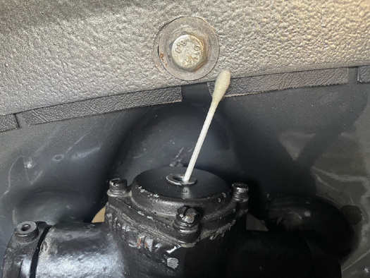
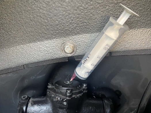
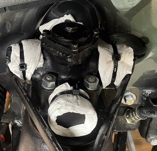
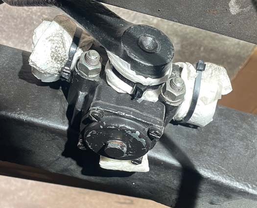

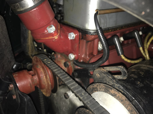
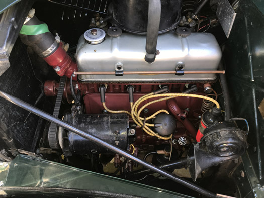
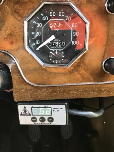
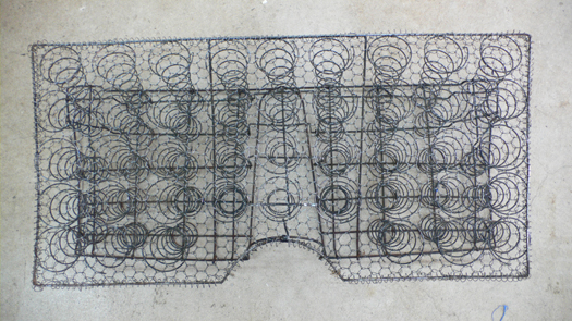
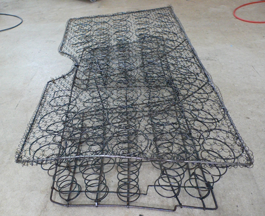
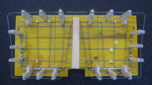
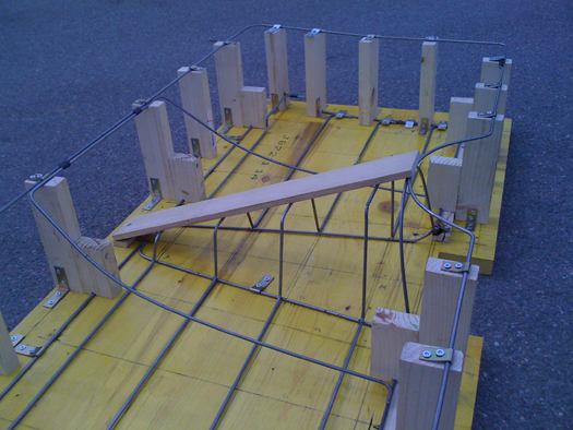
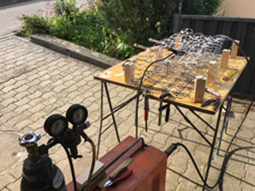
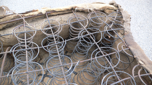
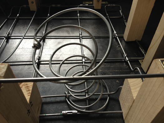
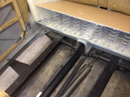
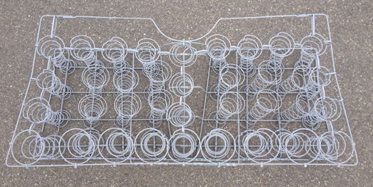
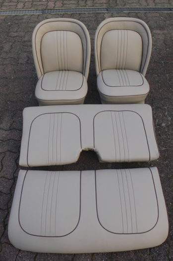
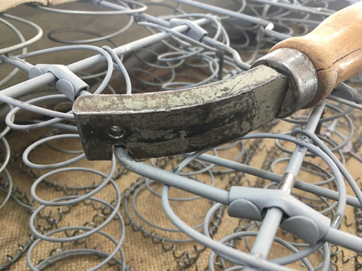
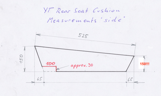
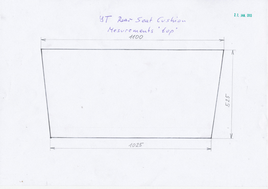
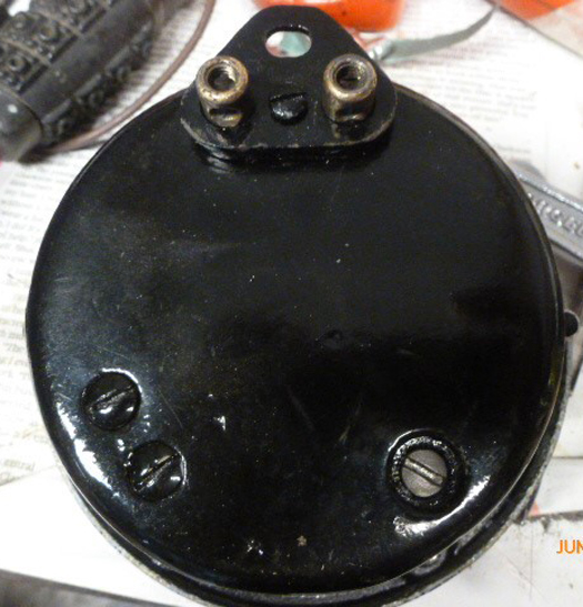
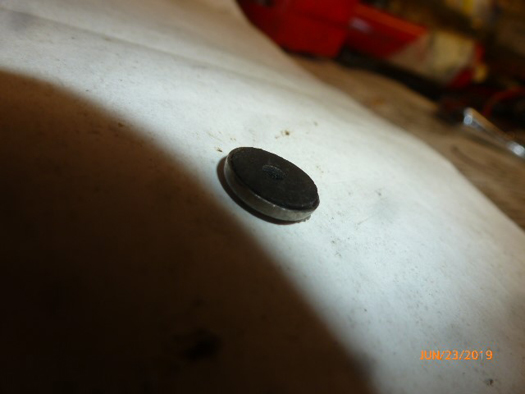
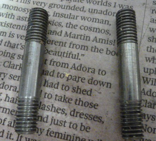
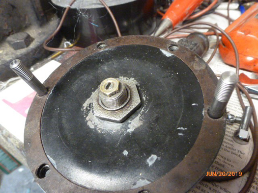
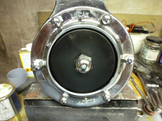
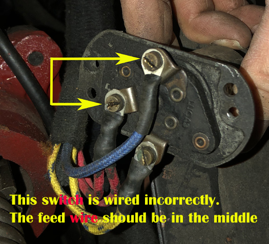
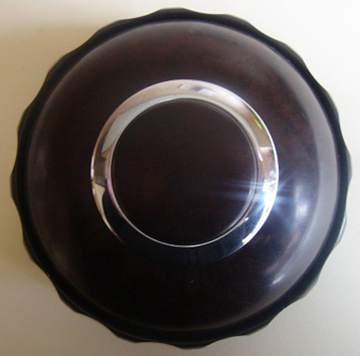
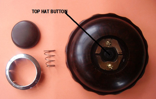
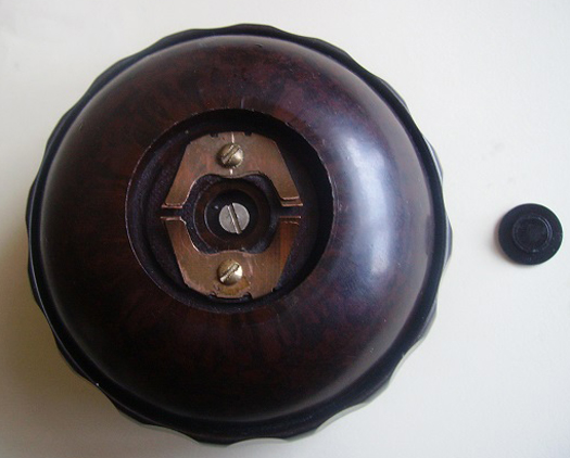
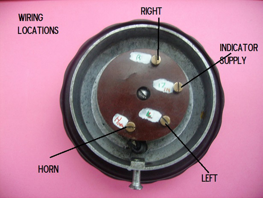
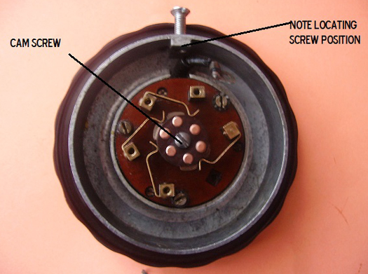
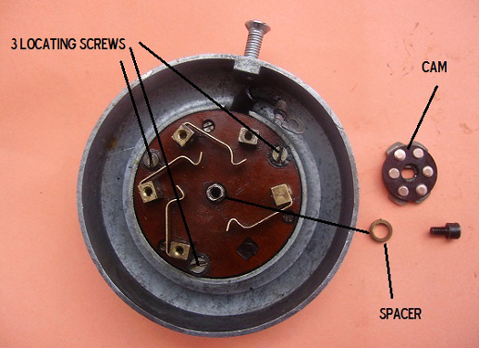
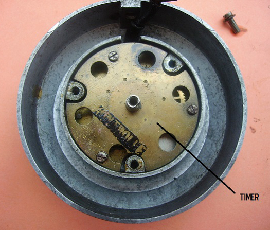
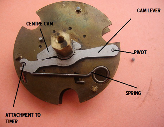
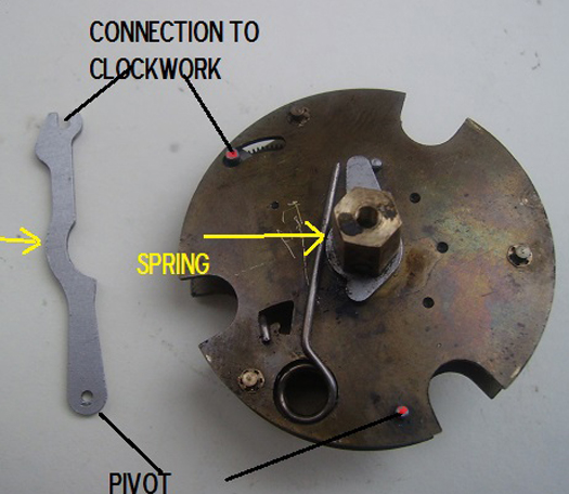
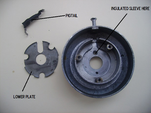
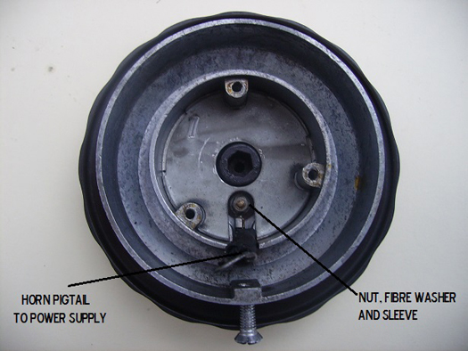
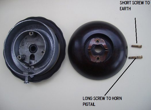
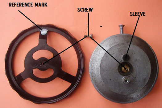
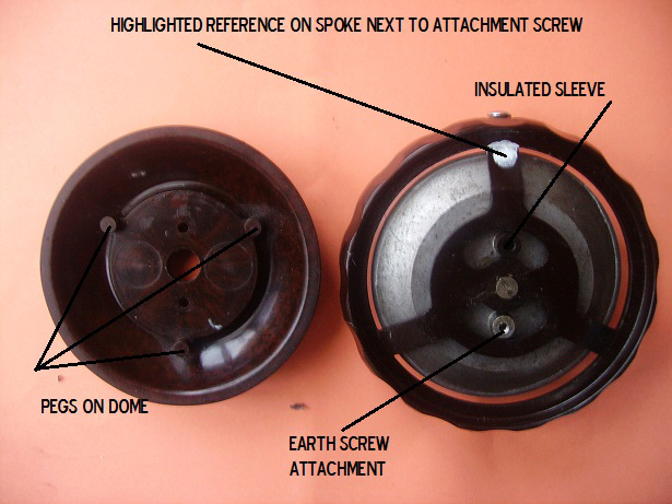
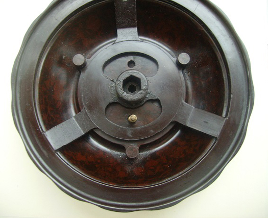
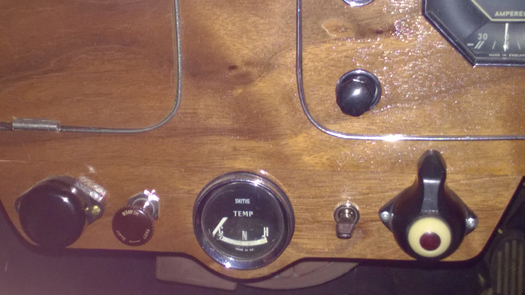
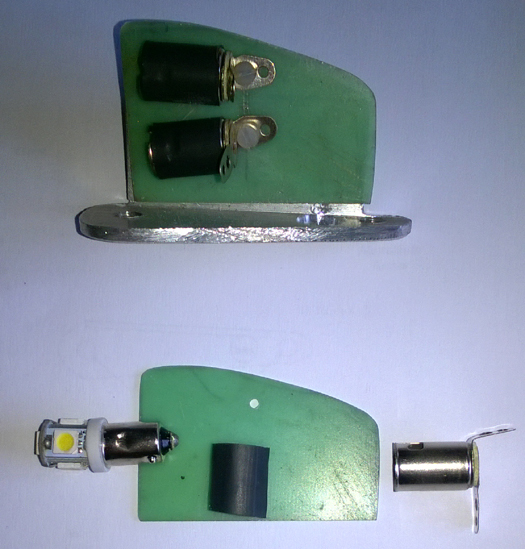
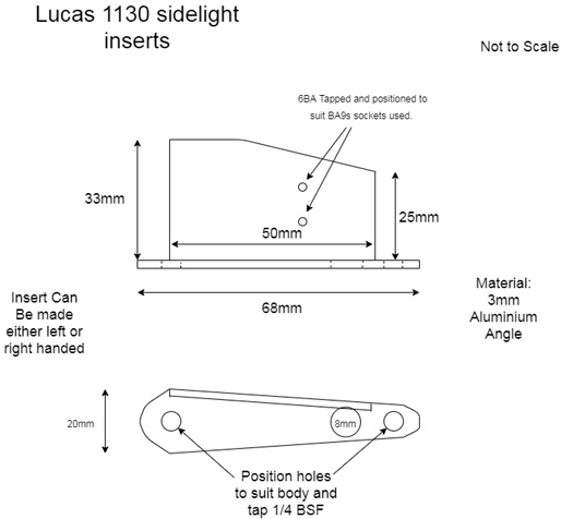
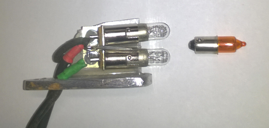
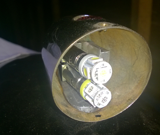
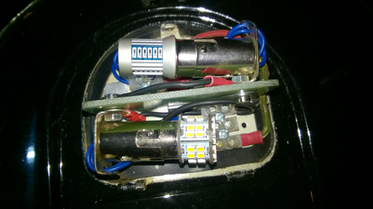
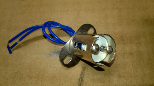
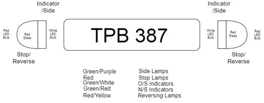
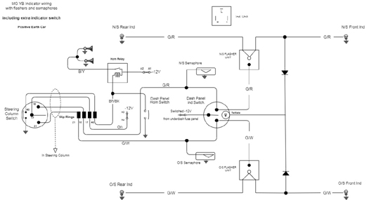
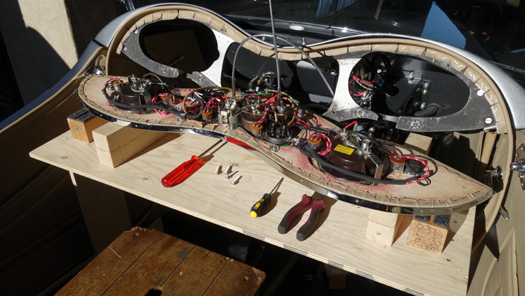
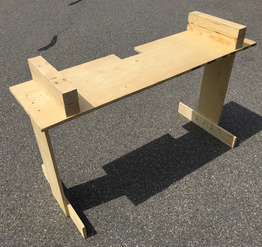
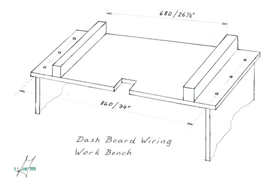
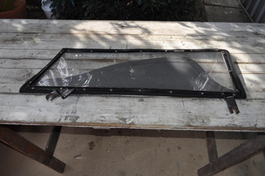
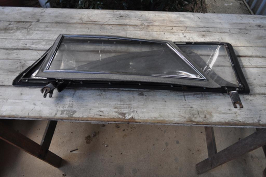
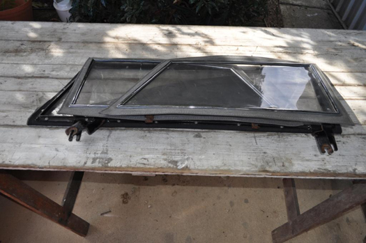
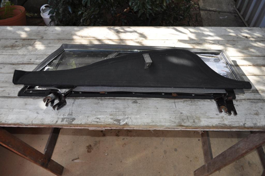
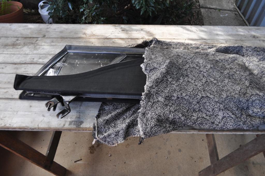
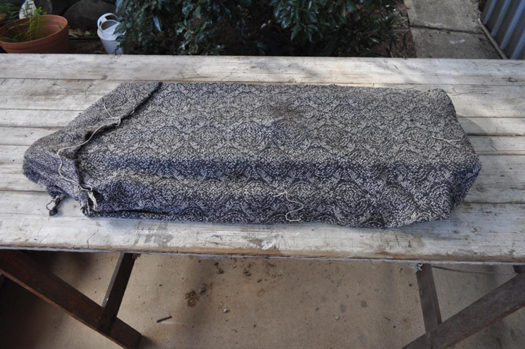
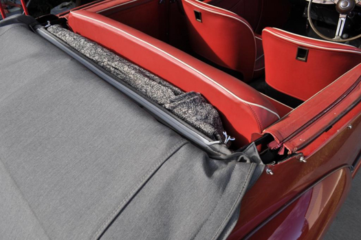
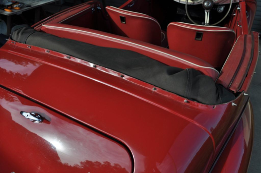
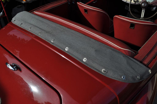
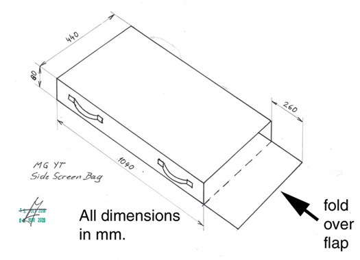
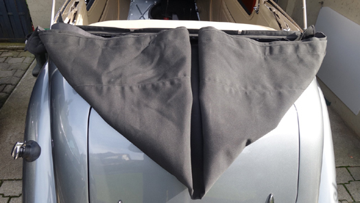
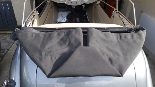
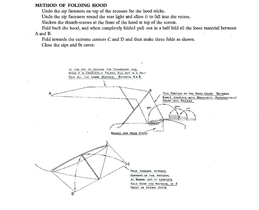
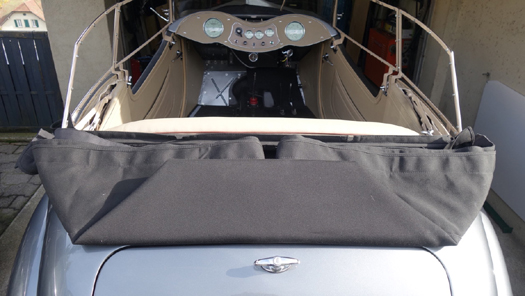
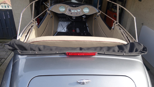
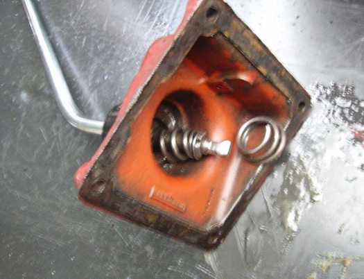
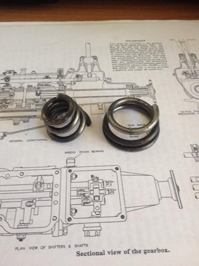
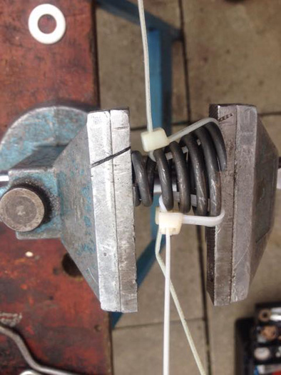
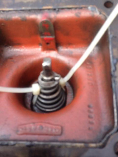
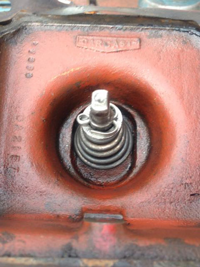
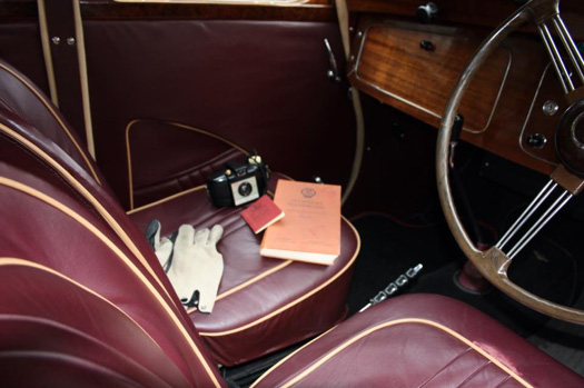
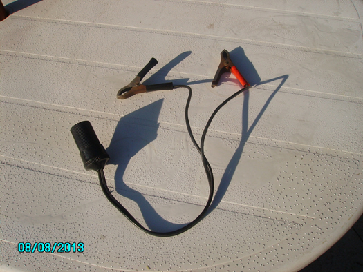
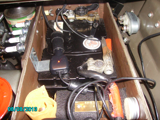
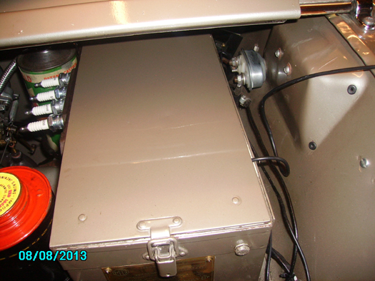
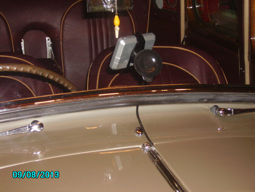
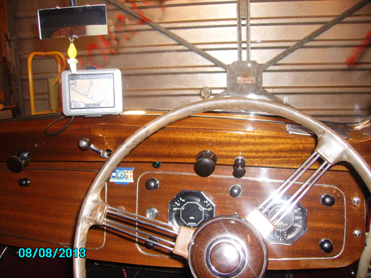
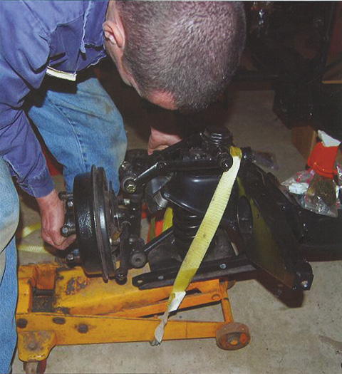
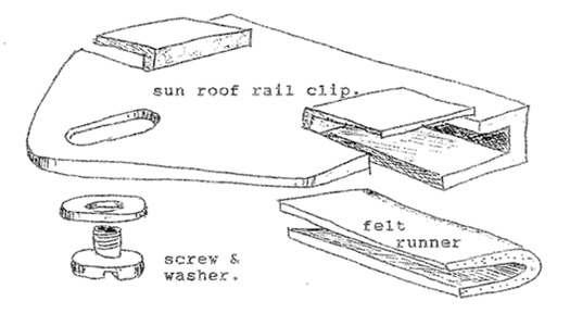
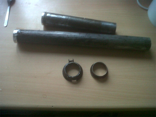
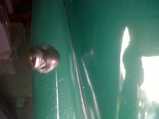
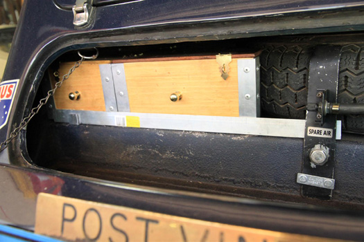
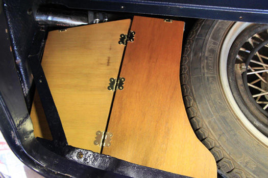
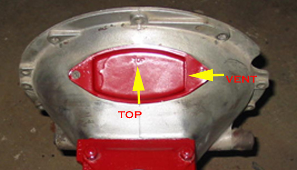
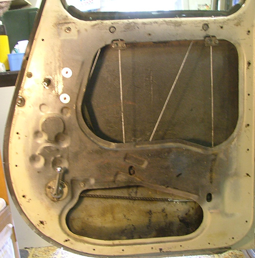
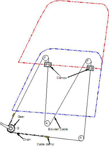
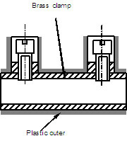
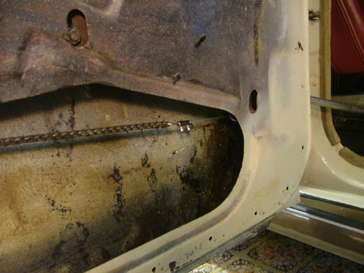
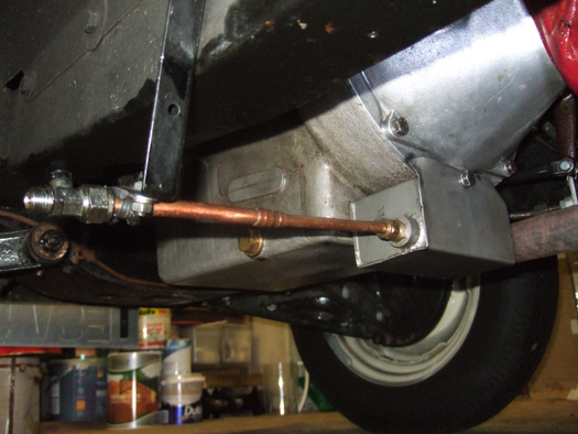
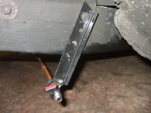
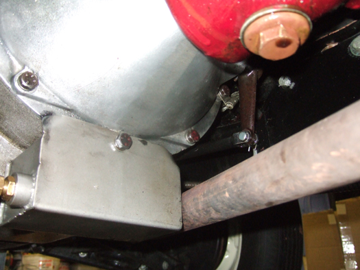
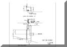
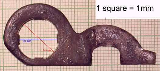
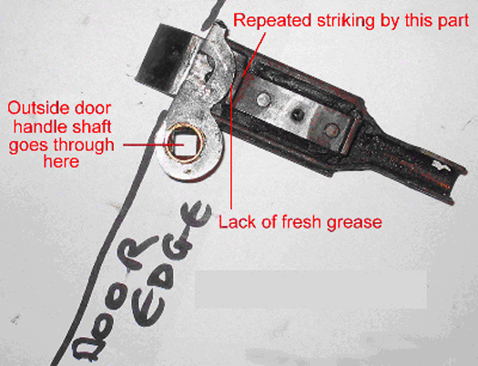
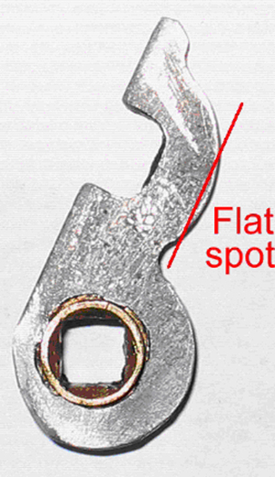
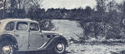
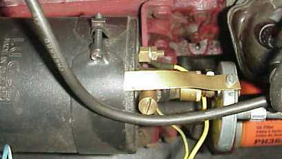
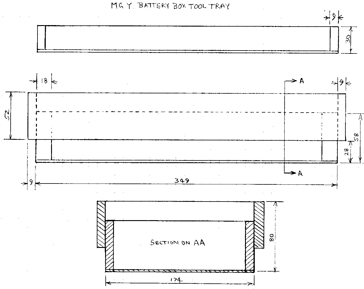
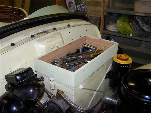
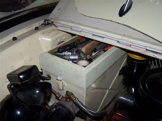
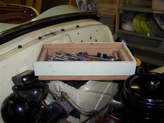
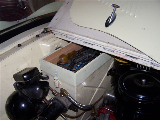
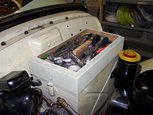
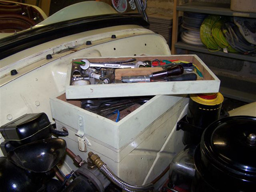
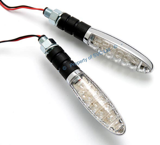
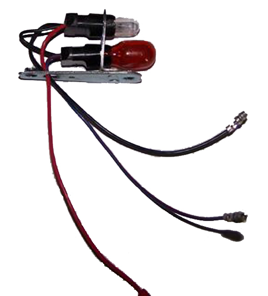
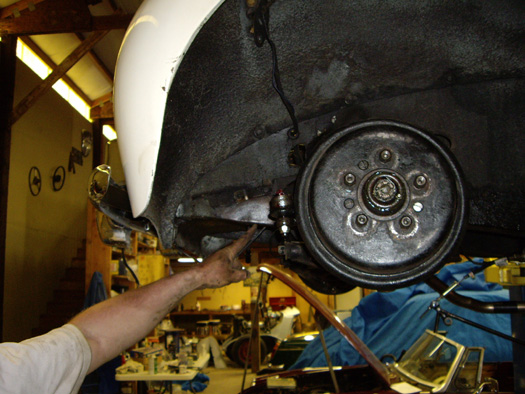
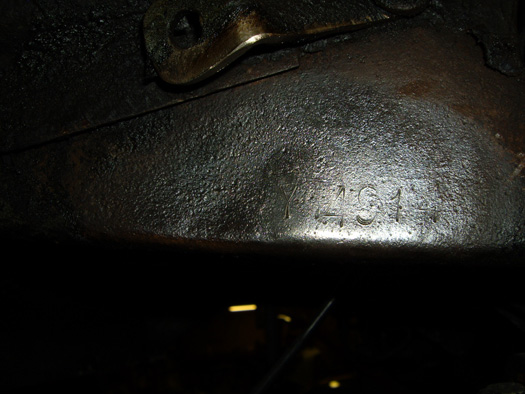
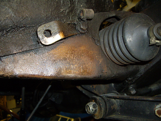
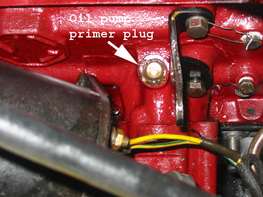
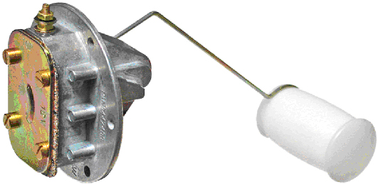
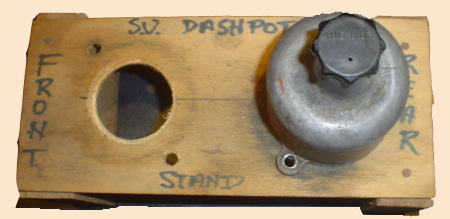
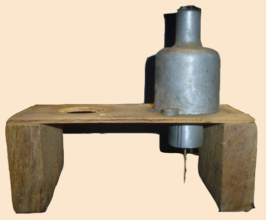
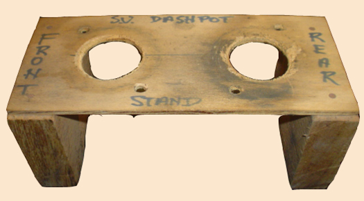
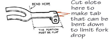
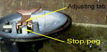
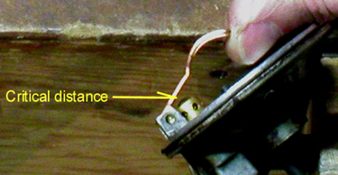
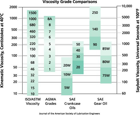
 The replacement pattern water pump is supplied without an essential washer. It is easy to be misled into thinking that all that is needed is supplied as the pump comes complete with Woodruff key and stiff nut, so it appears that all one has to do is slide the pulley in place and secure with the stiff nut. The seemingly insignificant washer is not supplied; probably because it is a non-standard size. However, without this washer distributing the load only the outer edges of the stiffnut bear onto the edge of the pulley recess, while the centre of the stiffnut is pulling tightly on the thread of the shaft. With the side pull on the pulley by the driving belt the net result is that the inner surface of the stiff nut becomes bevelled and resembles a small wheel nut!
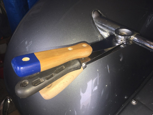