|
|
|
|
|
|
|
|
|
|
|
|
|
|
|
|
|
End of Menu Items |


Overhaul of SU Fuel Pumps Used On MG TA, TB, and TC Type Midgets, and Y Typesby Clifford F KnightE-mail: cliffknight@tiscali.co.uk |
S.U. electric fuel pumps are amongst the most reliable fuel pumps found on older cars providing they are properly serviced and maintained. When supplied new with MGs they could be expected to easily outlive the engine without adjustment. Our cars and all their components are now well past their design life, yet many of us are still using original fuel pumps. They will still operate, albeit unreliably, with eroded and incorrectly set contacts, poorly adjusted diaphragms and partially blocked filters. Often a sharp tap will restore a stalled pump to life for another month. This ability to just about keep working with no maintenance, has unfairly given the product a reputation for poor reliability.
The following instructions should allow any enthusiast to restore an SU fuel pump to as new specification and reliability. The work requires no special tools and very little skill. Even if you are new to old car maintenance and restoration, please try overhauling your SU fuel pump yourself. You will derive a lot more satisfaction than paying an expert to do the job or buying a renovated pump.
There is nothing more satisfying than sitting behind the wheel of a TA, TB or TC on an open country road listening to the change in the frequency of the tick from the fuel pump as you pull up hills or accelerate to pass a slower vehicle ... and knowing that the tick sounds correct because it is correct because you made it so.
DESCRIPTION
The S.U. fuel pump used in MG TA, TB and TC cars was a 12 volt, low pressure Type L electric pump designated AUA 25. The same or similar pump was used on many British cars from 1930 to 1960 and they are readily available at autojumbles.
All early cars were fitted with pumps with brass bodies. A two part aluminium body was introduced in 1948, but no alterations were made to the part numbers and the exact introduction date is unknown.
A side effect of the improving octane levels of post war fuels was a tendency for vapour locks to form in under bonnet pumps. A high pressure pump was introduced on the TF, installed at the rear of the car near the petrol tank, thus preventing fuel vaporisation problems due to higher under bonnet temperatures. That pump had a slightly longer body than the L type (2¾ in. as against 2¼ in.). Many post 1950s British cars used HP pumps with 2¼ in bodies. Care should be taken to distinguish the correct pressure type for use on TA, TB and TC cars as the higher delivery pressure of the HP types may cause flooding at the carburettor and the reduced lift may cause fuel starvation with a low fuel level in the tank.
A GUIDE TO DISTINGUISHING L FROM HP TYPE PUMPS
The following identifiers should help when purchasing second hand pumps with tags missing.
All HP type pumps incorporated a condenser and had a bulge in the cover alongside the terminal post, whilst all L type pumps had flat end covers.
Earth screws on L type pumps were the same size as the flange fixing screws - 2 BA. HP pumps used smaller 4BA screws. Very early L type pumps used an extended stud in place of an earth screw.
L type pumps were supplied as either 6 or 12 volt. The voltage was marked on the moulded end cover. Also wiring insulation was red for 12 volt and green for 6 volt (when 6 volt pumps ceased all insulation was changed to black plastic).
L type pump outlet valve cages had 2 holes and HP pumps had 4 holes.
Note 1: The Morris Minor AUA 66 pump is identical apart from the delivery pipe connection, which can easily be changed. This is probably the most widely available SU pump.
Note 2: I have seen several minor differences in the outside of the magnet assembly case. Some have a short pipe for the outlet; some have a small web near the flange. They all seem to be interchangeable with one exception (see below). I have no idea which is "correct".
ORIGINAL SPECIFICATION - TYPE L PUMP
Maximum suction lift from bottom of fuel tank to pump: |
42 in. |
Delivery head from pump to carburettor: |
Max. +6 in., |
Output: |
8 gallons per hour |
Bore of pipe: |
0.25 in. |
Maximum line pressure: |
1.5 lb/in2 |
Nominal voltage: |
12 V |
Minimum voltage: |
9.5 V |
CONSTRUCTION OF THE FUEL PUMP
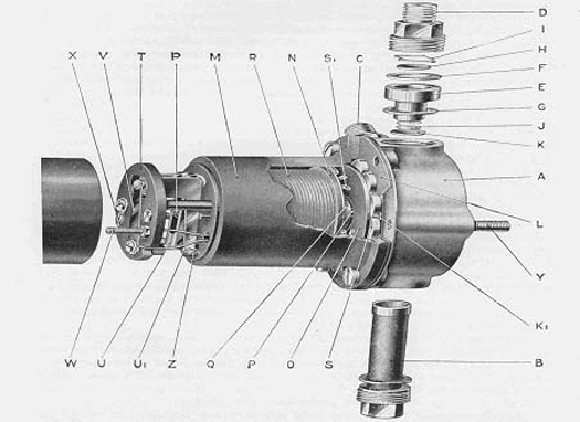
The pump consists of four main assemblies: the body A, the diaphragm assembly L, the magnet assembly M and the contact breaker assembly T.
The body is either a hollow brass stamping on early pumps, or a two part aluminium casting held together by the screws which secure it to the cast-iron coil housing. The screws are longer than those used with the brass type and are not interchangeable. A filter B is screwed into the bottom. The inlet union C is screwed in at an angle on one side and the outlet union D is screwed into the top. The outlet union screws onto the delivery valve cage, which is clamped between two fibre washers. In the top of the delivery cage is the delivery valve, which consists of a thin brass disc H held in position by a spring clip I. The suction valve is a similar disc K and rests in a seating machined in the body. Holes connect the space between the valves and the pumping chamber which faces the diaphragm and magnet assembly M.
The diaphragm assembly is clamped at its outside edge between the magnet housing and the body and in the centre between the brass retaining plate and the steel armature. A rod is permanently attached to the centre and passes through the magnet core to the contact breaker which is located at the other end. A spring is interposed between the armature and the end plate of the coil. The diaphragm assembly should be replaced as a single unit.
The magnet assembly consists of a cast-iron pot having an iron core on which is wound the wire coil which energises the magnet. Between the magnet housing and the armature are eleven spherical-edged rollers S which locate the armature centrally within the magnet. Some later pumps used a plastic guide clip in place of these rollers. I have also seen magnet assemblies with a larger diameter spigot, which I suspect is the HP magnet assembly. That magnet can foul the normal bore in the L diaphragm assembly. I'm not sure which model this was as I bought it as a supposedly restored brass bodied AUA 25 unit without any labels. Do check that your replacement diaphragm can seat properly and does not foul at the spigot in the magnet assemble.
OVERHAUL AND ADJUSTMENT
The contacts are relatively easy to clean and reset without disturbing other settings. The filter and valves can also be cleaned and replaced without full disassembly of the pump. Replacement of contacts, rocker mechanism or diaphragm will require the pump to be fully dismantled.
CLEANING AND RESETTING CONTACTS
- Remove terminal nut, connector, shake proof washer, rubber seal or tape, and Bakelite end cover from pump.
- Unscrew 5 BA screw securing washer, coil wire, and contact blade to the pedestal.
- Clean contacts with light emery.
- Replace blade, screw, coil wire and washer.
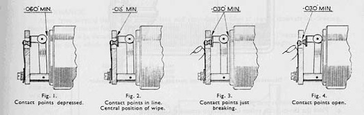
- Ensure that the blade just rests on the ledge on the Bakelite pedestal when the contacts are open. If the blade has become distorted it may be necessary to bend it slightly. Do not over tension.
- Ensure that the wiping action of the contacts is symmetrical when they fully open and shut. The contacts should be in line at the point that contact is just made or broken. There is considerable adjustment available in the blade mounting to achieve this important setting.
- Finally check that the points open clearance is 0.030in min.
SETTING THE "WIPE" OF THE POINTS
VALVES AND FILTERS
- Remove inlet and outlet unions C and D
- Remove the circlip I in the outlet valve cage and examine the inlet and outlet discs H and K for wear
- Replace as necessary
- Examine the valve seat in the body and the valve cage E for corrosion
- Clean as required. If the seat in the body is too pitted to clean up it will be necessary to replace the body
- Remove filter and clean with brush. Replace if damaged.
- Replace any damaged washers and reassemble in correct order as shown in main assembly drawing.
REPLACEMENT OF DIAPHRAGM AND/OR CONTACT BREACKER MECHANISM
Safety note
The original diaphragms fitted to SU pumps are attacked by some of the aromatics used in modern fuels. Failure of the diaphragm could allow petrol to pass through the coil into the contact cover where sparking may ignite the fuel or flow out of the vent onto the hot exhaust pipe. Replacement diaphragms for older SU pumps using materials designed for modern fuels are readily available. If you intend to use a second hand or old SU pump you are advised to replace the diaphragm, regardless of apparent condition, with a new one sourced from a reputable supplier.
Dismantling
- Remove Bakelite end cover as previously described.
- Undo 6 x 2BA screws securing magnet assembly to base. These slot headed screws can be very tight in the later aluminium bases due to corrosion. Use a good quality screwdriver or small impact driver to prevent damage to the screw head slots.
- Carefully prise the base away from the diaphragm and magnet housing.
- Carefully prise the edge of the diaphragm away from the magnet housing.
- Unscrew the diaphragm assembly anticlockwise from the magnet housing. The end of the diaphragm rod will unscrew from the contact rocker assembly. Be prepared to catch the armature guide rollers as they fall out. If resistance is felt, lubricate the threaded end of the rod in the contact assembly. Remove return spring and impact washer.
- Unscrew 5 BA screw, securing washer, coil wire tag, and contact blade from the pedestal.
- Unscrew 2BA brass nut, washer, wiring tag, and lock washer from terminal post and carefully remove the post from the pedestal.
- Remove 2 screws, washers, lock washers, and wire securing pedestal assembly to magnet housing. Carefully remove pedestal assembly.
- Rocker mechanism can now be replaced if required by sliding the hardened pivot pin out.
Reassembly and adjustment
- Inspect Bakelite pedestal, rocker mechanism, pivot rod and contacts and replace any damaged parts.
- Clean contacts as required.
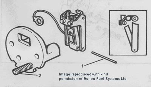
- Invert pedestal and fit the rocker assembly to it by pushing the steel pin through the hole in the rockers and pedestal struts.
- Position the central toggle so that, with the inner rocker spindle in tension against the rear of the contact point, the centre toggle spring is above the outer rocker spindle as in the inset below.
- Check that the throw over mechanism is not binding. If necessary the rockers can be squared up by bending the arms carefully with thin nosed pliers.
- Assemble the square headed terminal stud to the pedestal.
Refit pedestal to magnet assembly using the 2 x 2BA screws. One screw has a spring washer under the head whilst the other, which serves as the earth terminal, should have a spring washer in contact with the pedestal and the tag of the earth wire from rocker mechanism directly under the screw head. Do not over tighten as the pedestal is easily cracked.
Refit the spring washer, coil wire tag, lead washer, and dished brass nut to the terminal screw. The correct order is shown below:
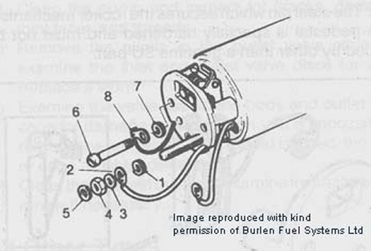
- Spring washer,
- Terminal tag,
- Lead washer,
- Coned nut with cone towards lead washer.
- Fit Bakelite end cover then sealing washer 5
Assemble diaphragm spring with the large diameter towards the coil. Position the impact washer onto its groove in the armature on the diaphragm assembly. Insert spindle into coil assembly and position the 10 armature guide rollers into their locating groove (or fit plastic guide clip on later units). Screw the diaphragm assembly spindle into the contact rocker assembly.
Hold the magnet assembly horizontally and press the diaphragm firmly with the thumb and check to see if the contact rocker throws over.
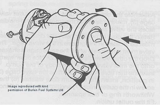
If the rocker throws over, screw the diaphragm assembly in until it just ceases to throw over under thumb pressure. Back of until it just throws over, then unscrew by 4 holes. Continue unscrewing a little until the diaphragm lines up with the holes in the magnet assembly. Check that the rocker still throws over under thumb pressure. This adjustment must be made with the contact blade removed.
- Refit blade and adjust contacts as already described.
- Align coil assembly with base and fit screws finger tight. Take care that the rollers remain in position and do not trap the diaphragm. Note that the drain hole in the coil assembly should the same side as the filter in the base.
- Insert a matchstick under one of the rocker mechanism rollers to hold the contacts together and connect the pump temporarily to a 12 v supply. This will excite the armature and pull the diaphragm in. Whilst the diaphragm is under tension tighten the 6 screws securing the coil assembly to the base.
TEST THE PUMP
The important aspects of fitting the diaphragm are:
- The contact breaker blade must be removed when the diaphragm is adjusted.
- The diaphragm must be pressed with a steady pressure and not jerked when setting.
- The diaphragm must be stretched to the limit when the body screws are tightened.
When satisfied, check that all internal wiring is tidy, refit the Bakelite end cover, lock washer and brass nut.
Refit sealing band or tape the end cover gap.
NOTES ABOUT CONTACT LIFE
The pumps fitted to T-ABC cars had no spark arresters. The current switched is about 3 amps so some contact erosion will occur. Providing the car is used regularly, the wiping action should keep the points in good condition for considerable mileage. When car radios first started to appear, SU fitted a capacitor to reduce sparking. To retrofit this you will need a later end cover with a bulge. The capacitor is wired across the points and is not polarity sensitive.
Most SU pumps supplied now are fitted with a zener diode as original equipment. For positive earth installations as on MG T Types fit a 24 volt zener diode. The positive terminal (usually marked with a band) should be connected to the rocker blade screw and the negative to the terminal stud. It should be possible to fit the diode within the standard cover.
Some later pumps were fitted with double contacts. Whilst this may increase contact life on an L type pump, the reason SU introduced the change was to accommodate higher currents in heavier duty coils.
A NOTE ABOUT SPARES
Burlen Fuel Systems are the owners of SU and are responsible for the distribution of SU products throughout the world. They also publish an excellent workshop manual and reference catalogue for SU products used on classic British vehicles. They can supply everything from individual washers to complete pumps and even electronic contactless conversions.
Burlen Fuel Systems - http://www.burlen.co.uk/
I have no connection whatsoever with this company other than as a satisfied customer.