|
|
|
|
|
|
|
|
|
|
|
|
|
|
|
|
|
End of Menu Items |


Restoring Jackall jack rams
By Neil Wakeman
Download a PDF copy of this article here.
Fellow Y owner, Malcolm Hickman and I embarked this week on a journey to restore the Jackall jacks on our respective cars — Malcolm's because his rear jacks were leaking, and mine because they were an unknown quantity and it's easier to restore them whilst undergoing the complete restoration of my car.
During the course of a 1936 Morris 12/4 restoration many years ago, I tried to restore the jacks for that, but didn't really get to first base. Older and more stubborn now, and with valuable help from Malcolm, we've persevered, and been successful. Hopefully what we have learnt will help somebody else.
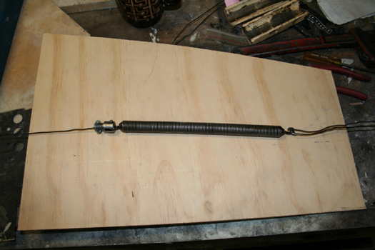
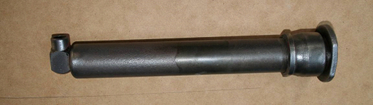 This is the complete unit, a rear jack as it happens but the front one is exactly the same, only it's a bit longer. The workshop manual provides a good drawing of the jack's innards, but unfortunately is silent on the subject of pulling it apart!
 Malcolm and I found that there were two major problems — undoing of the housing E from the outer tube, and unscrewing the jack foot, which is screwed into the inner tube B.
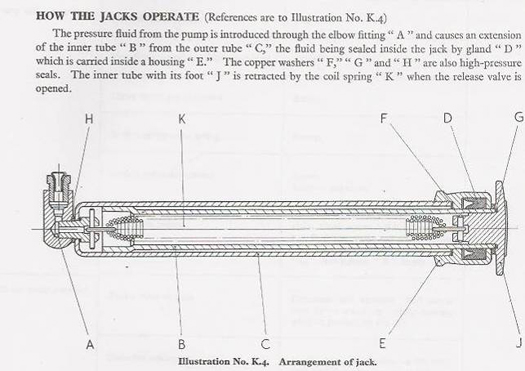
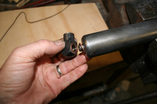
First step was to unscrew the elbow fitting A which released the inner tube with internal spring — this enabled the partial withdrawal of the inner tube still with its foot attached. This cannot be completely removed until housing E, which is screwed to the end of the outer tube, has been removed.
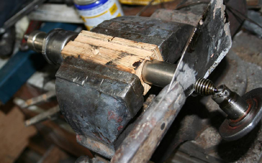
Unscrewing the housing E requires a sturdy bench vice, a very large spanner (in my case, I used a plumber's adjustable pipe wrench) and a length of steel tube on the handle of the wrench, to increase the leverage. To stop the cylinder from rotating in the vice, I bolted up the rear jack mounting bracket to each jack cylinder in turn, and locked that into the vice. Application of a significant amount of brute force on the extended wrench handle was successful in undoing the housing from the external tube.
With the housing unscrewed, it is now possible to withdraw the inner tube with the housing and the foot attached. The return spring is still inside the inner tube at this stage, as is the housing E which can't be removed until the foot has been removed.
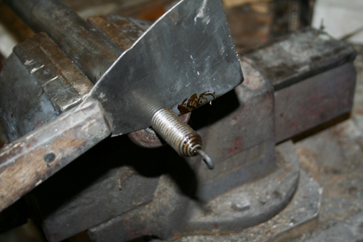
 Now comes the tricky part — how to unscrew the foot which is screwed inside the inner tube, and has been since about 1949. It is the inner tube which seals against the gland/seal D, and must therefore be treated with care. No plumber's wrench on this part!
First, we tried a solid red gum block about the same width as my vice jaws. This block had a 1" hole drilled up the centre, and was split lengthways. The tube was placed in the block and then in the vice, but was no match for the force required to undo the jack foot.
Next we called upon the services of Reg, a friend of Malcolm's, who works in a large engineering factory. Reg disappeared into the works area with a couple of the inner tubes, confident that he'd be able to remove the feet for us, only to return half an hour later looking sheepish and admitting defeat. He had tried everything — locking up the shaft in a large four jaw lathe chuck, a huge spanner with extension bar, whacking it with a hammer, using heat from a blow torch, and still no success.
Malcolm and I then discussed some alternatives, finally settling on some radical surgery with a hacksaw to perform a "footectomy", cutting through the tube at its base, hard up against the foot itself and stopping when we'd cut through the tube wall. Very conveniently, there's a groove in the foot, right at this point, so the process didn't harm the foot casting at all.
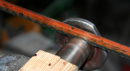 This was a complete success enabling the foot to be screwed out of the shaft by hand. Our inner tube is now a tiny bit shorter — the width of the hacksaw blade plus about 1 mm, plus another tiny bit once the hacksaw cut is cleaned up in a lathe.
There's still plenty of thread remaining inside the tube to accommodate the foot when it is reassembled and to provide a seal between the foot and the end of the tube. Although it was originally assembled dry, relying on copper washers at the joining faces, our plan is to also use a modern hydraulic thread sealant to make sure it can't possibly leak.
With the foot unscrewed, but still attached to the return spring, it was now possible to remove it. With the inner tube still locked in the vice, the return spring was pulled out of the tube and held in place by the innovative use of a paint scraper, inserted between the coils to temporarily take the tension. This now enabled us to remove a small pin in the foot which was holding the hook of the return spring, releasing the foot from the spring.
 A length of welding wire bent in the middle to hook over the attachment hook in the end of the spring and pulled lengthwise to take up the tension, enabled the removal of the paint scraper and a controlled release of that tension. Alternatively, if you don't mind a game of hide and seek, simply remove the paint scraper, then go look for the spring on the other side of the workshop.
With the foot now detached, it's possible to remove the housing E. The old gland seal G was then dug out of its recess in the housing to complete the dismantling operation, and the assembly now looked like this.
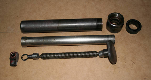 Top: Outer cylinder, housing, gland (seal)
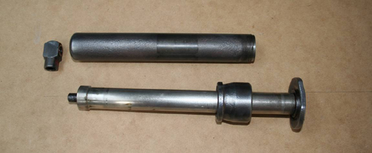
Centre: Inner cylinder tube (now about 2.5 mm shorter than original)
Bottom: Elbow fitting, lock washer (to stop the spring anchor rotating when the elbow fitting is tightened or loosened), return spring with anchor fittings and foot attached.
Some other points:
We'll need a number of small replacement bits, most notably new gland seals (available from SVW in UK, and J C Ludowici in Australia), copper washers in various sizes (sourced from a local hydraulic hose service centre), serrated lock washers, some hydraulic sealant.
On one cylinder, the serrated lock washer inside the cylinder had broken and no longer performed its intended function. As I unscrewed the elbow fitting, it kept turning, rotating the spring inside the cylinder. To overcome this problem, I drilled a 3mm hole in the outer cylinder and inserted a pin hoping that it would be in the right place to slip into the slot in the spring anchor to stop it turning. Sometimes we can be lucky because it worked! Just need to weld up the little hole now.
 Oil that is sixty years or so old is putrid! The stuff that was in these jacks was like black treacle, smelled horrible and was unbelievably sticky. All the photographs supporting this article were taken after cleaning. Readers who embark on a project of this nature should not expect to be working with nice clean bits like this!
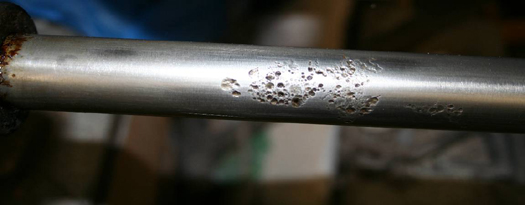
Before reassembly, check the inner tube for corrosion or damage, as it is this component that runs inside and seals against the gland. I have a problem with one of my jack tubes, which is badly corroded, and I will need to seek advice from an engineer friend to see it it's possible to repair or replace this component. Somehow, I don't think I will be able to buy a new one down at the local spare parts shop! I am hoping that I don't have to have a new one made but if I do, for most machinists, it's apparently not a difficult item to replicate.
REASSEMBLY
 Malcolm and I have now completed the reassembly of our jacks and have now found the most effective process, mostly by trial and error.
1. First step is to install a new seal into the housing E. This is a bit tricky because there's not much room, so be very careful not to damage the lip of the seal — you'll probably need something to push it in with, but don't use anything sharp like a screwdriver. We used a piece of wooden dowel.
Push the housing with the new seal over the end of the inner tube. Again, be very careful not to damage the new seal, bearing in mind that you are pushing it in against the seal. I made up a small polished wood tapered insert, like a bullet head, on my wood turning lathe, inserted that in the end of the tube, and this worked well. Some rubber grease on the lead-in was helpful. Put that sub assembly aside for the moment.
2. To fit the return spring into the outer tube, thread a length of wire (we used welding wire) through the hole in the spring anchor and bend it slightly to stop it coming out as it's threaded up the tube. Don't twist it around the anchor, as you're going to need to pull it out before the elbow fitting can be screwed on.
Hook the spring eye to its anchor, and then hook another length of doubled-over wire to the other end of the spring. You're going to need to use this to stretch the spring once the elbow fitting has been tightened.
 Secure the outer tube in your vice. Feed the single wire through the hole in the end of the outer tube, and draw the end of the spring anchor though this hole. Hold it with a screwdriver or similar, so that it does not fall back into the outer tube, and remove the draw wire. Install a copper washer to the end of the spring anchor, then screw the elbow fitting on, and tighten fully.
 3. Now take your inner tube sub assembly and thread the doubled-over length of wire, attached to the spring, through it. Slide the inner tube all the way inside the outer, collar end first. Screw the housing on to the end of the outer tube.
4. Pull the spring out of the tube using the doubled-over draw wire, and insert a suitable blade (eg a paint scraper) into the coil, leaving about 30 — 40 mm of spring sticking out.
 Remove the draw wire and fit the jack foot to its hook on the end of the spring. Take up the tension on the spring, remove the paint scraper, and release the spring tension, allowing the screwed end of the jack foot to be drawn into the inner tube. Carefully screw the foot into the inner tube — note that it is under some tension, so make sure it's not cross threaded before you start screwing it in.
5. Last task is to tighten up the housing E and the jack foot. The housing is the easy one — hold the outer cylinder in a vice and tighten it. To tighten the foot, it will be necessary to pull the inner cylinder out some distance, against the spring, and hold that tight in your vice, using wooden blocks to avoid damaging the surface of the cylinder. When you've tightened up the foot, put the assembly into the vice, pull the foot out a little to release the blocks (watch your fingers as you release the tension) and the job's done!
 Useful aids for the job
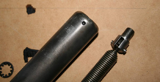
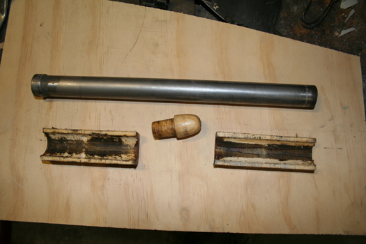
Rounded knob slips into the end of the inner tube, to help when inserting it into the housing and the new gland/seal, without damaging the gland lips.
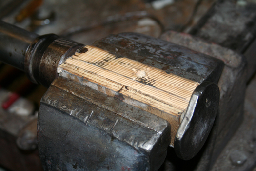
Scrap timber about 40 mm square, with a 1" hole drilled up the middle, sawn in half lengthways to hold and protect the tube when mounted in a vice.
Hydraulic sealant applied to all threads during assembly.
Neil Wakeman
2nd February 2011
Note: Any opinions expressed are solely those of the author and do not necessarily reflect those of the International MG Y Type Register.