|
|
|
|
|
|
|
|
|
|
|
|
|
|
|
|
|
End of Menu Items |


YT 3208 - a YT(B) 
Richard Prior has modified his YT by adding a B Series engine from an MG B. Here are his comments and some photographs of his car.
The pundits will be very quick to point out that the factory never produced a tourer version of the YB saloon. However the "B" in this case represents the MGB components used in what has become a very reliable highway cruiser and competition special. The car is very much a wolf in sheep's clothing but I am sure Cecil Kimber would have built a similar car if he and the parts were there at the time.
This story begins in the mid seventies with two little children who found it increasingly difficult to squeeze into the back of our 1950 TD so what better than a Y Tourer. A very dilapidated and dismantled YT was available with TD running gear, no engine and gearbox and of course standard options with Y Types no spare wheel compartment, boot or sills.
From the outset the car had to have the reliability of a modern MG and the capacity to cruise all day at 70 MPH and not brake a crankshaft. The extra performance was icing on the cake. The bottom line it had to be all MG, look like a YT and structural changes minimal and restorable.
An MGB 18V series 5 bearing engine with 4 synchro OD gearbox was fitted to the standard Y front engine mount by fabricating a new "U" shaped bracket. The engine was positioned as low as possible with only 12mm of clearance between front corners of the engine and front cross member and similar between the back of the engine and firewall. A section of the tubular chassis member that supports the gearbox was removed and relocated a little lower and a bracket fabricated to support the "V" configuration of the gearbox mount. Lowering of the gearbox was necessary to give a direct line to the back axle. The overall location brings the gearstick directly below the dashboard - just right and the only structural change required to the whole car including body work. However, a new gearbox cover, tail shaft cover and toe board were fabricated to accommodate the larger gearbox with overdrive this also means new floor board support rails and floor boards. A shortened Wolseley 4/44 tail shaft completed the drive train. The few original bits that came with the car were put aside.
The rear axle is standard MGB wire wheel banjo type with standard YT springs. The axle tube spring mounts were removed and new ones fabricated incorporating Jackall and Panhard rod mounting points and refitted 12mm further out each side to accommodate the wider Y spring spacing. I used 50mm spacer blocks to achieve the required ride height. These could be built into the spring mounts but spacers enable adjustment. The backing plates where refitted to their opposite sides and rotated so that the handbrake levers line up in the original position for Y type. Lengthening the handbrake levers improves mechanical advantage. The original hand brake is retained and cables made by a local supplier to suit. Not having original rear dampers Mini front gas telescopics were used to fit the narrow gap and brackets fabricated using the original chassis mount holes to locate them in the vertical position. These dampers (shock absorbers) do not have a lot of travel so their location is critical as is location of the bump stops.
The front suspension employs standard Y bottom wishbone and spring pan with MGB lever dampers, king pin assembly and disc brakes. The springs are shortened MGB. The only work required to fit the MGB bits is drilling two new holes for the dampers. The out board holes are further apart and also foul the top of the spring therefore a 10mm plate is sandwiched between the top of the spring and the underside of the cross-member which is drilled and tapped as captive threads. MG midget tie rods fit directly to the Y rack and pinion and are the right length to pick up the B steering arm and ball joint. The other addition to the front end to control that Y Type body roll is a 24mm anti sway bar. Mounting brackets and Nolathane bushes are off the shelf from a good suspension shop.
There are also some shots of rear shocker conversion below. I will try and give an explicit description of the shots below so that they make some sense. First of all no apologies for all the dirt, I haven't washed the underneath for a while but the YT is a well used machine and we often travel on gravel roads.
Mounting bracket template.This is my cardboard template of the mounting bracket. The two 3/8" holes at the bottom marry up with the original shock holes in the chassis. The large oval hole in the middle is for the handbrake cable and allows for up and down travel. Ignore the two small holes, the one at the top is top mount for the shocker. The bracket is 10mm thick and the shape allows it to sweep up and to the rear of the car up into the cavity above the axle housing. The brackets are the same for both sides and fit on the outside of the chassis. As viewed in the photo they would fit looking across the car if the front of the car is on your left and the rear on your right. Normally I would refer to the nearside and offside of the car but I am not sure if this is the same in the US.
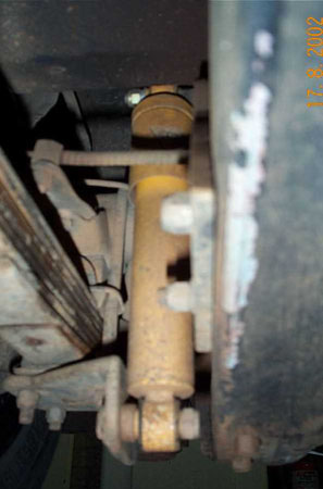
Rear suspension #1.This shot is looking rearwards on the passenger side of a right hand drive vehicle. You can see in this shot how the bracket leans rearward up into the axle cavity and keeps the shocker vertical and in front of the axle tube. The bottom bracket is simply a piece of shaped angle iron mounted via the axle U bolts underneath the original base plate. The bottom shocker pin is forward of the U Bolts.
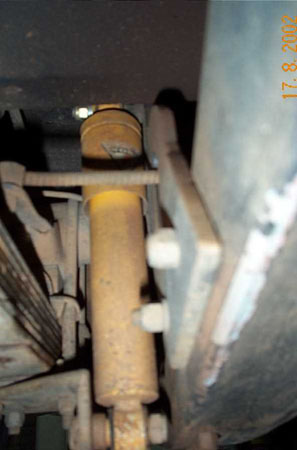
Rear suspension #2. This is drivers side (RHD) looking rearward. In this shot you can see the extension for the handbrake cable anchor. This rather lengthy extension was necessary because I have also lengthened the handbrake levers to try and improve mechanical advantage which is still fairly ordinary.
Rear suspension #3. This is also the drivers side (RHD), here you can see the handbrake cable passing through the cut out.
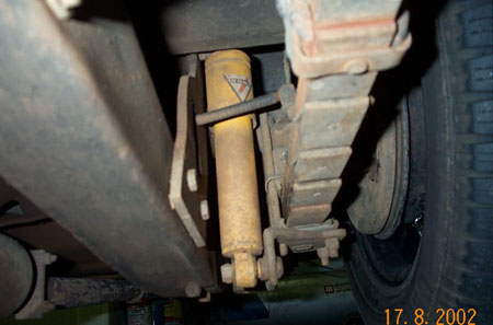
Rear suspension #4. This shot is looking from the middle of the car across to the drivers side (RHD). Here you can see the shocker bracket reaching back up into the axle cavity. You can also see the more substantial axle bump stop and hoop I fabricated and the hand brake cable coming through the bracket. The other business in the foreground is a modern electric fuel pump and fuel filter that pushes the fuel through the original SU pump that is still in place butthe electrics disconnected. The other smaller device is a suppressor for the CB radio.
Brakes as previously mentioned are standard MGB and because a clutch master cylinder was also required the original and almost non existent pedal box was removed and an MGB one welded into position upside down. A friendly machinist made a new and longer pedal shaft to suit the new pedal spacing and a supporting bush fitted at the inboard end. The clutch and brake pedals (standard Y) are now further apart operating MGB master cylinders. In hindsight an MGA twin cylinder unit would have been a better option but they don't grow on trees.
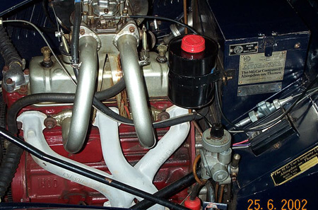
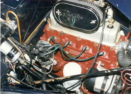
Returning to under the bonnet the original MGB twin SU carbies where initially used with ZB Magnette air cleaner manifold and oil bath air cleaner to give the engine bay a period appearance and confuse the experts. The front of the manifold required a large chamfer to fit inside the bonnet side but it was concerned that this may have been restricting air flow to the front carbie. Recently long sweeping induction tubes where fabricated by son Luke (one of the kids who was supposed to occupy the back seat but was 20 before it was finished in 1992) to accommodate a 45DCOE side draft Weber carbie that is located over the rocker box. This configuration works extremely well looks fantastic and the petrol heads nod almost speechlessly in approval.
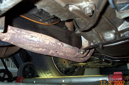
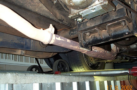
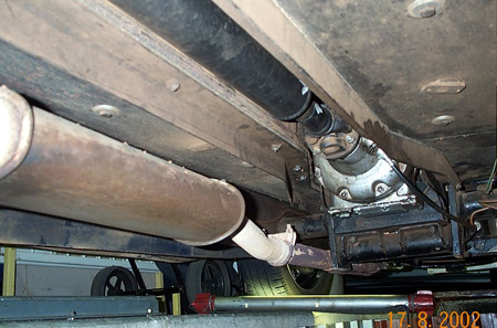
The exhaust system is a standard MGB system,manifold and engine pipes. The original cutaway in the chassis is fortunately in the right spot for clearance of the rear engine pipe. The end of the engine pipe clears the underside of the front tubular cross-member then a slight upward bend to get the muffler a bit higher, then a sweep down under the next tubular cross-member and there it is suspended from the original location. From here is a Hotdog then a home made bracket on the rear tubular cross member (see pictures below).
The petrol heads continue to be amazed when the other side of the engine is exposed and they notice the distributor is sitting up on top of a nicely curved metal stork. You can hear their brains working overtime "yes its driven with an 8mm flexible cable I admit and put them at ease." The cable runs in a spiral outer like a large speedo cable which in turn is supported within the outer tube. This wonderful little duvalaky (invention) was required because with the engine in its low position the steering column passed straight through the distributor cap - not the ideal location. Because cable whip was anticipated with points ignition these were replaced at the outset with an Allison pointless electronic ignition. This combination has been faultless for 55,000 miles. Yes the cable becomes a little sloppy after about 10,000 miles but the electronic ignition copes well with any variation and maximum advance is set at 32deg. rather than worry about static or idle timing.
Because clearance for the steering column was still tight the original was replaced with a solid rod splined at the bottom end where an MGB universal joint made the connection to the Y rack. The top end inside the car passes through a nylon bushed outer and a TC spline to accept a Brooklands steering wheel.
Continuing under the bonnet the standard Y radiator was used but the large central opening in the header tank blanked off and a smaller opening fitted to the offside and the bottom outlet moved to the nearside to match the B engine configuration. The water pump fan was removed (no room) and a small electric thermostatically controlled fan fitted in front of the radiator behind the grill as was the oil cooler. This required making a new headlight support bar with a large semicircle bend to support the electric fan. The cooling system is not pressurised but the radiator cap is a positive seal and a small catch tank on the overflow keeps water loss negligible. The engine steady assembly is simply a bracket very similar to the original and mounted on the cross member but not as high with a thick rubber block through bolted to the U shaped engine mounting bracket and rubber bushes under the bolt head and nut.
For the electric's an internally regulated alternator was used and the original regulator served as a junction box. A one off wiring loom complete with cotton braiding for a touch of originality was made with engine electric's on the offside and included OD wiring, indicators and an extra wire to the rear for a modern rotary gear fuel pump. The original SU pump remained just for show and emergencies. All chrome 8 inch headlights (they look much better than 7's on a tourer) with modern quartz bulbs were fitted. At the rear for safety's sake modern plastic lenses were cut 'n' shut and moulded into 2 extended "D" shape lamps to include stop/tail/reverse/indicator and using festoon bulbs. Not having the original column horn button or floor dip switch a TC/D type horn and dip switch was mounted under the dash on the RH side together with the OD switch. The indicator switch was also under the dash immediately above the gear stick.
The layout of the dash is original in appearance except that TD2 speedo & tacho are used and duel oil pressure/water temp gauge. The tacho has electronic innards and an inline reduction box fitted to the speedo cable to correct cable turns, the result being two very accurate and serviceable instruments.
The colour scheme for the car was decided many years ago when two grey leather hides where acquired at the right price. The doors are in the original pattern with pockets however the seats are 2 inch pleats all over which is far more interesting than the original style. More recently the front seats although comfortable in a straight line were replaced with ergonomic seats with adjustable slides and rake that did not rock 'n' roll around every corner and made a big difference to the driveability of the car. With grey interior the exterior had to be dark blue the final selection was 1940's "Packard blue light" selected because it did not have the redness of a navy blue. The finishing touch was 15 x 5 inch 60 spoke centre laced chrome wire wheels that were specially built for the car so that the wheels sat just inside the wings. The spare wheel was also designed to fit the very narrow space provided by keeping the wheel centre in line with the 4 inch rim and fitting a 15x135 Michelin tyre used on Renaults, it easily fits into the original storage space.
The car was finally finished literally the night before heading off on a 4500 mile round trip to Tasmania for the '92 national meeting. Since then it has made the trip across the Nullarbor and back in '93, '96 and back to Tassie again at Easter '98, now completed 55,000 miles. Top speed is just over 90mph and standing quarter loaded 18 secs. As a package the car looks fantastic, is a real buzz to drive and does everything it was hoped it would do and more with the trophies to prove it.
This project has very much been a family affair and would not have been completed without the help and motivation from the two kids, Luke and Rachael, who were supposed to sit in the back but fortunately grew up with MGs in their blood and where of great assistance. Also to my wife Barbara who rubbed her fingers to the bone sanding panels, made and fitted a lot of the interior trim and kept us going with cups of coffee and meals at all hours. She also allowed me to use the holy of holies the lounge room to store the painted panels and use it as an assembly area for the windscreen, side curtains, bonnet and all the chrome goodies etc. Thanks gang.
RICHARD PRIOR
10 MANSEL PL.
DUNCRAIG 6023
WESTERN AUSTRALIA
PH +61 (0)8 9448 0089
Here are some of his photographs. Click on them to enlarge.
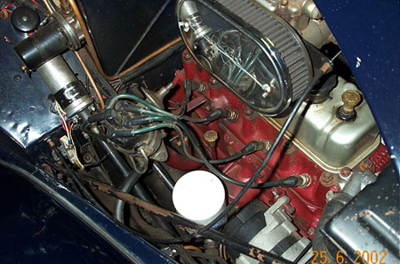 Distributor in situ |
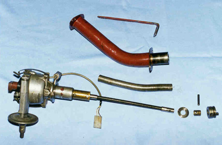 Distributor flexible drive |
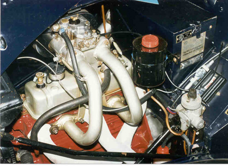 Carburettor and Manifolds | |
 Engine right hand side |
 Engine left hand side | ||
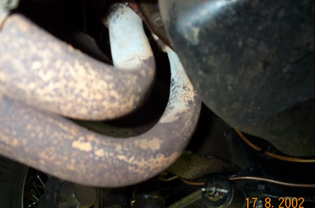 Standard MGB engine pipes. You can just |
 The bracket coming off the bottom |
 After passing under the first tubular brace | |
 A better view of the upward sweep |
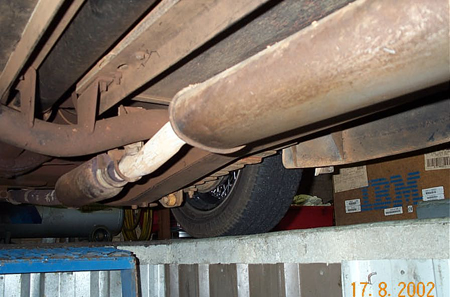 Rearward view shows a crank down again to | ||
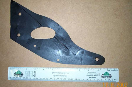 Mounting bracket template |
 Rear suspension #1. |
 Rear suspension #2. | |
 Rear suspension #3. |
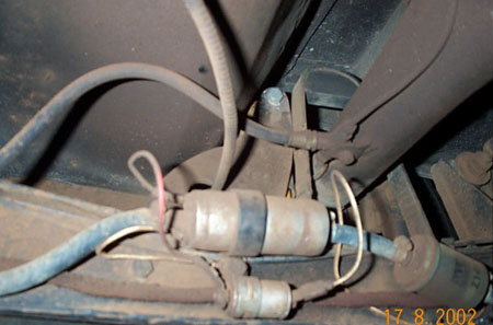 Rear suspension #4. (Mounting bracket can be seen behind the fuel filter) | ||