|
|
|
|
|
|
|
|
|
|
|
|
|
|
|
|
|
End of Menu Items |


Technical Q & A Advice |
 |

This is not an "all makes and models" service and it is only intended to cover MG Y Types. Other models will not be addressed here.
Disclaimer
Please Note read our disclaimer before attempting any mechanical or other modifications or methods referred to herein.
Welcome to the Technical Corner. We cannot hope to be able to cover every problem you may come across, but a problem shared is a problem halved as they say, and there may be others out there with the same problem. The service is available free to all owners of an MG Y Type, however we would also respectfully add that we cannot offer advice on any other models or make of car that you may own in addition to your MG Y Type.
|
If you have any handy hints or tips you'd like to share with other Y owners, please contact either of our Technobods (Tony Slattery and Paul Barrow) us via our Contact Us page and supply details of the your suggestion and we will contact you for pictures or more details. You should hopefully receive a reply within a few days. |
|
Index to Technical Queries | ||||
|
|
|||
Although the original article refers to a Morris 10 (at least I think it does - webmaster) and "Preparing the car for your Holiday Motoring", the techniques shown here are very valid for preparing our MG Y Types for a new season's motoring too.
![]()

An article on how to tune single and twin carburettors was published in the June 1981 edition of The Sacred Octagon and is reproduced here.
![]()
A great article on how to care for your distributor was published in the May 1949 edition of the Nuffield Products in-house magazine The New Outlook on Motoring and is reproduced here.
![]()
Question: What size radial tyres can be used on a Y/YT and how do you fit them?
Reply: I use 175/75R16 radials on my Y here in Australia, however you cannot legally fit a 175 radial on a 3 inch rim in Australia, so you need wider rims. This is how I have worked around it.
I use Lada Niva rims, welded to Y-Type centres – as they are a 4WD rim they are also a bit heavy. You can also use Standard Vanguard rims welded to Y-Type centres, but getting hard to find. Steve Brompton used some Nissan rims I think that were narrowed – legal to do in New South Wales, but not here in Queensland. Here we are not allowed to split the rim – narrower or wider, the rim must be unmodified.
The van tyres come up on eBay every now and then for bargain prices (I have paid as low as $82AU each including freight to my door) – this is because they are getting old and cannot be sold if they are more than 8 years old, so the retailers/wholesalers dump them at cost. The tyre manufacturers suggest changing tyres when they are 10 years old, however this is based on the tyre being exposed to sunlight every day. The tyres on my YT are now 18 years old and show not signs of UV damage. Our cars spend most of their lives in the garage, so we can probably expect 20-25 years of life. You certainly won’t wear out a set of van tyres in this time on a Y-Type.
I have both 175/80 and 175/75 sizes – both work well on the Y’s. The YT tyres are “Hankook”, the YA are “Marangoni”, and I have a new set in a dark storage of “Federal”. Back in the md-1990’s these sizes were available from Bridgestone and Falken. Some of the tread patterns look a bit chunky (M+S – Mud & Snow rated), but they work well, especially in the wet. They give you confidence to drive the car in any weather.
Tony Slattery
Disclaimer
Please Note read our disclaimer before attempting this modifications. This modification, although included on this site, is not necessarily endorsed by the International MG Y Type Register. Before contemplating or attempting this modification, please check with your local laws and also with your insurance carrier before making any changes.
![]()
Question: How do you remove the sun roof from an MG Y/YB?
Reply: Removing the Y-Type Sunroof
The Y-Type sunroof, or "sliding head" is a pretty simple and effective form of air conditioning. In combination with the opening screen, it can make travel in hot climates very refreshing and civilized.
So how does it work — firstly the handle — the roof locks in position by turning the handle through 90 degrees. This lifts the back edge of the panel and pushes to against the fixed roof panel. Conversely, unlocking lowers the back edge so it can slide below the fixed roof panel.
The panel slides on a lip of steel at each corner of the sliding panel — form a "V" with two of your fingers and drop your other hand into the "V" little finger first — this is how the "V" slides on the lip. When new the "V" slides were made from felt — unfortunately over time this felt can rot and even be eaten by insects, so it is rarely there when you pull an unrestored roof from a unrestored car. Some people like to put new felt back, while others I know have tried leather as well. My personal choice is felt that has been treated with wax — this provides natural lubricant, without attracting grit and resisting moisture.
To service the sunroof you need to remove it from the car — there are no shortcuts, so make the decision to do it properly. It can be done by one person, but it is a whole lot easier with two people.
Unlock the roof. If you do not see it drop at the back, the rubber strip at the back stuck to the fixed panel may be stuck to the fixed roof panel. You need to free this up so that the rear of the sunroof drops: use your imagination, but try not to dent the steelwork or scratch the paint.
Now that it has dropped, slide the roof to the rear about 4 inches (or 100mm if you are a younger person). It could be hard, but you need to persist, try rattling it side to side, up and down, anything goes, just get it back. Next, remove the sunroof handle — don't loose the retaining screw — it is special, and don't drop the handle on your toes — it hurts. Don't ask me how I know this.
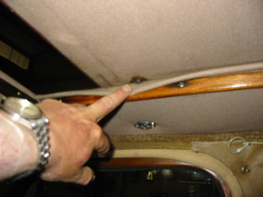 At each front corner of the sunroof, peel the lining back about 3 inches from the front edge of the panel. You should see a single pan-head slotted screw. The Y-Type workshop manual says you need to remove the side timber strips to gain proper access to the screw head. On original cars this is certainly necessary, but if the felt strips are gone the panel can be moved sideways to get to the screw head, remove the screw completely (catch the star washer if it is still there).
Push the panel sideways the other way to remove the screw on the other side. Now push the two little slides retained by those screws towards the outside of the car — if you have pushed it far enough you should be able to lift the panel up on the front corner by an inch or so. Once both sides are free to lift, it is time for another pair of hands. Lay a folded tea towel or soft cloth at each front corner of the roof opening — this is to protect the paintwork from being scratched while you remove the panel.
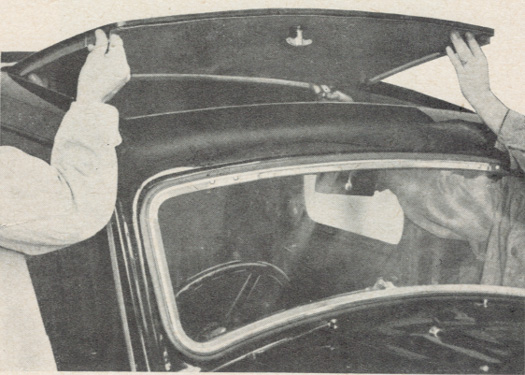 Position each person on either side of the car standing up — put one hand through the door window opening and lift the front edge of the sunroof high enough to slide over the front of the roof. Grab the front edge of the sunroof with your other hand and together pull the panel forwards — it should slide forwards until the rear runs out of "lip", then you can keep pulling forward — keeping the panel as low as possible, because there is a central flat spike you should now see in the centre of the roof. Once the panel has cleared the spike you can lift it away from the car by walking forwards and carrying the roof panel over the bonnet.
Lay the roof panel upside down on a padded table — examine how those front slides work and lock into the lip on the side of the roof opening. Also examine the two metal tags at the back corners that should have felt on them — probably long gone, and try to understand how each tag goes above and below the lip hidden in the fixed roof. Also examine where the flat spike goes into the panel. Once you have understood how the roof works — re-fit the handle to see how it locks too — you are then ready to start the servicing proper of you sliding head panel.
Sunroof slide clip 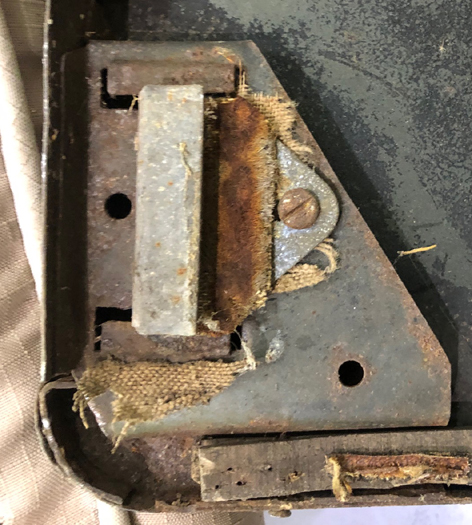 |
Sunroof latch 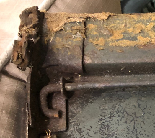 |
Sunroof latches 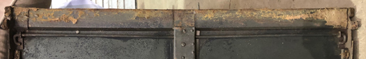 |
Full view of underside of sunroof 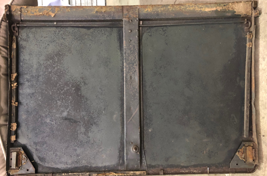 |
Full overhead photograph showing channel for rear seal seal is not present 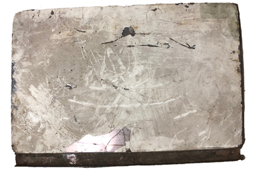 |
![]()
Question: What should I use to top up the shock absorbers please?
Reply: Use an SAE 20 oil, one that will not foam. I use motor cycle fork oil.
![]()
Question: How do I replace the brake shoe liners please - I have new liners and rivets?
Reply:Step 1 - drill out the old rivets.
Step 2 - find some kind of metal stake to hold in a vice that is the same diameter as the head of the new rivets.
Step 3 - (You need three hands for this bit) Start putting the rivets in from the centre of the brake shoe and work outwards. If you start at one end you may find that by the time you reach the other end, the holes in the new linings don't match up with the holes in the brake shoes.
Step 4 - Insert the first rivet through both lining and shoe then invert the assembly so that the rivet head sits on the stake held in a vice. The exposed rivet that you are about to bash should have a hollow centre. Use a centre punch to start opening out the rivet uniformly then continue with a suitable hammer. This is why you need three hands. You'll be trying to balance the assembled items on the stake with one hand, holding the punch with the second hand and the hammer is in your third hand. There is always one rivet that is difficult to work successfully. It's the one that conveniently sits close to the spigot that holds the return spring. Just do this one as well as you can.
WHEN REPLACING BRAKE SHOES - ALWAYS WORK IN PAIRS OF WHEELS AT ENDS, FRONT WHEELS AND REAR WHEELS. DO NOT WORK ON SIDES. REPLACE ALL SHOES AT THE SAME TIME IRRESPECTIVE OF WEAR.
![]()
Question: I have just finished restoring my YB, but the body mount in front of the rear seats fell of ages ago, does anyone have a photo or sketch of it please?
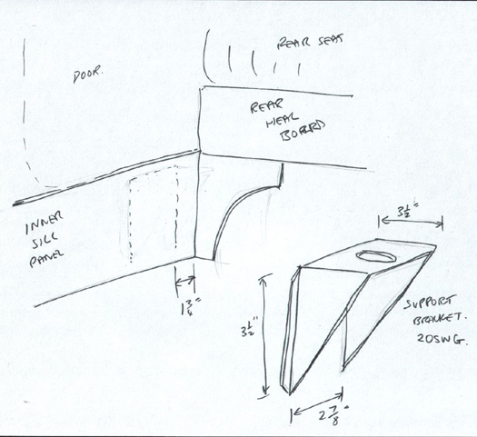 Reply: The sketch attached shows the body mounting on the 'C' post, that just in front of the rear seat heal-board. It is of 20swg thick mild steel, (thicker will do no harm.) It is 3.5 inches square and 2 and 7/8 inches wide. It is welded onto the inner sill panel about 1.75 inches in front of the heal-board. Its top surface sits level with underneath the wooden floor, that means the wooden floor has a reveal to clear the bolts head. I would NOT drill the hole for the bolt until you have the body sitting on the chassis. You will no doubt have to make allowances for slight differences in measurements, especially on a repaired body/sill area. The mount sits on top of the chassis outrigger that supports the front end of the rear spring. It is normal to have to put the odd thick steel washer under mounts to level up the body, and to ensure all mountings sit firmly on their seats.
![]()
Question: I have an XPAG that I pulled from the remains of a Y beyond salvation and am now in the process of acquiring a YT Chassis without power train. Besides the inlet manifold, air cleaners, exhaust manifold and twin carburettors, what else do I need to change to bring the standard XPAG up to YT specifications please?
Reply: TC camshaft and distributor advance weight spring, (you can get away without them though they do give a more correct advance curve). The YT engine is a TC engine, so if you put all TC bits on and in it, you have a YT unit. Using the twin carburettors with a standard YA cam will not improve power very much. I would go for one of the more modern sine wave-ground cams of the type Brown & Gammons sell, they improve both power and torque.
![]()
Question: I have recently overhauled my Jackall Pump. What kind of fluid should I use to refill the system?
Reply: Non-foaming mineral based motor cycle fork fluid is nearest equivalent fluid nowadays - about 20 SAE.
![]()
Question: I've just acquired a Y Type gearbox (similar to the TD/TF box I think), which seems in good condition except for what the manual calls the interlock pin and its securing rivet, both of which are missing. The pin fits horizontally in the 3rd/4th gear selector rod at the point where the rod passes through the back of the gearbox. Its held in place by the rivet, but is still free to slide sideways slightly. This last item isn't a rivet in the conventional sense, in that it fits into a blind hole in the underside of thr selector rod. (What stops it from falling out?).
Still awake ?
MG obviously included these items for a purpose (I think to prevent more than one gear engaging at a time, which is clearly undesirable!), so I want to replace them before I use the 'box. Can anyone tell me where I can obtain replacements, or alternatively supply sketches so I can make them up?.
Reply: Dave DuBois from Washington State, USA, was kind enough to respond with some clear illustrations of the relevant bits scanned from his TD manual, together with his thoughts on the operation of the parts, all of which are reproduced below — many thanks Dave.
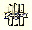 The pin and "rivet" which are missing in your 3rd/4th selector shaft are a belt and suspender approach to keeping the gear box from having two gears engaged at a time. In normal operation, it would be highly unlikely that two gears would ever engage at the same time unless the unlikely situation of the selector dog were to engage two selector shafts at the same time. Even then the two balls on either side of the 3rd/4th selector shaft or the shaft itself would have to be severely worn to allow it to happen. In the picture below (scanned out of the TD Workshop Manual), you can see where all three shafts pass through the rear bulkhead of the gear box (view from the top, looking down) and the balls between the shafts. Notice that the balls sit deeply into the 1st/2nd and reverse selector shafts and not in the 3rd/4th shaft due to the pin that goes through this shaft. This leaves the 3rd/4th shaft free to move back and forth and when it does, the balls lock out any motion of the other two shafts. Now, if 1st gear or 2nd gear are selected, the ball on that side will push the pin through the 3rd/4th shaft and stop not only it from moving, but also the reverse shaft from moving.
 This picture shows a sectional side view of the 3rd/4th selector shaft. This view shows the "rivet" that holds the pin in place.
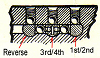 This final picture shows an end on view of the shafts where they pass through the gear box rear bulkhead. This shows the balls on either side of the 3rd/4th shaft and the pin that passes through it.
Armed with this information, I did some experimentation on my gearbox and came up with a solution as follows:
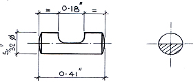
Measuring my 'box enabled me to sketch out an interlock pin, which was made up from 5/32 inch diameter mild steel rod. It was then installed in the gearbox (without the rivet at this stage) and checked for correct & smooth operation, just needing a little 'fine tuning' to get it spot on. The pin is shown in my drawing below, in its final as-fitted state.
 The so-called 'rivet' is not a rivet in the conventional sense, in that it fits into a blind hole in the underside of the selector shaft and has no head (at least mine doesn't, as there's nowhere in the shaft for a head to go!). Its purpose is to allow the interlock pin to slide freely from side to side by the requisite .090 inch in total, yet prevent it from moving any further and jamming the selector shaft.
So my 'rivet' was simply a plain, parallel, headless pin, as before from mild steel rod, this time turned to 0.094 inch diameter so as to be a light interference fit (i.e. a 'tap-in' fit) in it's hole. Having measured the depth of the blind hole, I made the rivet 0.380 inch long, 0.010 inch shorter than the hole so that once installed it sat just below the surface.
With the interlock pin in position, the rivet was tapped into place and a final check made that the pin was still free to slide from side to side. Then, to be absolutely sure that the rivet couldn't fall out I made a small centre punch mark in the selector shaft at the front edge of the rivet hole, just deep enough to displace a little of the shaft metal over the end of the rivet. All that remained to do was dress-off any raised metal around the punch mark with a fine file, and put the selector shaft back in the gearbox. It all works fine, and try as I will, I can't select more than one gear at a time!
Now for the health warning — the above shouldn't be taken as definitive MG, it's just my interpretation of the workshop manual illustrations with some fine tuning to suit my particular gearbox. If you have any questions, please feel free to contact me, Bill Bennett.
![]()
Question: I have a problem with a recently overhauled Fuel Pump that I fitted to my YT. It appears to be functioning well enough to pump fuel from a jar using a short length of hose but will not draw fuel from the tank.
The fuel line is ok as I have tried the pump from my TC and all works ok. The problem seems to be that the pump will not suck enough. The service manual states that it should be able to lift fuel 3 feet.
I have dismantled the pump and to the best of my knowledge everything is set to the correct settings. I paid particular attention to the adjustment of the diaphragm shaft. Any advice will be appreciated.
Reply: There are two sorts of SU pump, those that PULL and those that SUCK. The first kind lives under the bonnet (as per Morris, MG etc,), the other in the boot (as per Austin, Mini, etc). Is your pump an original, or is it one someone has fitted not knowing the difference?
Also, it is possible to assemble the non-return-valves incorrectly. They have a very smooth surface on one side of the disc, and are lightly knurled on the other. The smooth side must be the seated side, or the fuel can seep back. This making PULLING fuel a long distance very difficult. Also, what condition is your diaphragm in. When they get old they get stiff and pump poorly. I went for a modern solid-state one from Burlen, no points to worry about but it looks identical to the original.
![]()
Question: Can you give me an equivalent to Duckham's ZNOL Grease.16 shown on the lubrication chart for the brake cables?
Reply:Castrol LM. This one is a multi-chassis and bearing grease.
![]()
Question: I am thinking about fitting a new Cam Shaft to my YB. Do you have any recommendations please?
Reply: The best one currently available is a kit for a much better camshaft, followers and pushrods from Brown and Gammons (See Links page for full contact details). It has a much more modern profile, is much quieter, wider longer lasting lobes, more mid range torque. Those on the TC and TD are not that much different to the standard YB one. You can get a copy of Tuning MGs from the Octagon CC. It is by Phillip H Smith, old book but still relevant.
![]()
Question: Moss sell a rebuild kit for the Wheel Cylinders but after cleaning the accumulated road dirt from them I can't find how to dismantle them, can you give me some advise? Does the plunger pull out screw out or something else?
Reply: The piston often rusts into the cylinder. The only way to get the piston out is to try to rotate it a bit at a time, with lots of WD 40. If this fails, screw a bolt into the inlet threaded hole to block it off, then place a grease gun onto the LOOSENED bleed nipple, and pump away. You can get up to 1800psi with this, so do this in a safe place, as the piston MAY come out like a bullet! BUT more often they come out bit by bit.
Inspect the bore of the cylinder, if it is scored renew it, (or if a YA get it re-sleeved).
WASH OFF ALL TRACES OF WD40 AND GREASE with mentholated spirit, and then soap and water.
Under no circumstances must grease or WD40 contact the new rubber seals or the brake fluid. Once cleaned up, you can lubricate the piston with silicon fluid (as used by electricians). Do not let any brake fluid near any paintwork, it is a very efficient paint remover.
New cylinders can be had from MG Octagon CC, or if you just need new seals, from Lancaster Vintage Supplies on +44 (0)1524 423453.
![]()
Question: Could you help, I need some 1/4" od x 7/16" thread and 1/4" od x 1/2" thread brass male fittings for the Jackall system on my Y. Is there a UK supplier? Also what are the threads, are they BSP or NPT? Just a further question if you can help, What is the thread type on the sump and bell housing, they appear to be approx 1mm pitch (0.039"), but they are not BSF at 4TPI which is too course. Are they Nuffield metric? I would appreciate it if you can help me with these problems.
Reply: The entire Jackall system piping is British Standard Pipe Thread, which uses the inside-diameter of the pipe as its size, (i.e. a 1/4" pipe thread is about 7/16" diameter.) BSP uses a whitworth thread form. Plumber Suppliers will stock most bits. The only deviation is the flexible hose, it uses a very fine cycle thread, but the Register sells a pipe with a kit to get round this. ALL THE ENGINE THREADS are a unique French metric thread, as the engine was made by a firm who initially made guns in WW1 in France, Hotchkiss rt.Ci. Morris purchased the firm, called it Morris Engines, but the threads were used up and until 1956 on the Wolseley 4/44, and 1955 on the TF. The booklet "Lliving With The Y Type", written by Neil Cairns has a chart of what modern metric threads will fit. Nuts and bolts for the engine can be had from Mad Metrics on the same web site. You might also like to get the booklet " Living With The XPAG Engine". Both these books have far more info than one can get into a email answer.
![]()
Question: I intend to fit an electric radiator fan to my YA has anyone advice on where the thermostat switch should be fitted?
Reply: The ideal place is in the back of the header tank, as this is the 'top' of the system. However this will require the removal of the radiator. The other place would be into the top hose, but here you would need to fabricate a 'union' to fix into the hose, (like the early 1950s heater kits). Failing that you could braze a threaded union into the upper end of the thermostat casting, and fit a normal modern type 'waxstat' as per the modification in the booklet 'Y Type Information' by Neil Cairns.
![]()
Question: Could someone please tell me the correct way to set the engine steady bar correctly?
Reply: Let the engine sit on its mountings as normal, then adjust the bar until it holds the engine where it sits normally. It must not pull the engine one way or the other. Then tighten up the nuts to only just crush the rubber washers.
![]()
Question: How do I polarise a dynamo?
Reply: To polarise the dynamo Use a small piece of wire and momentarily (about one second) touch it between the regulator terminals marked "Al" and "F" or the way I do it get a long piece of wire from the 'LIVE' side of the Battery and touch the other end on the small terminal on the dynamo. It will make a few sparks so don't think you've hurt something. (John Arkley)
![]()
Question: I will need a new battery soon for my YB. What type of battery is suitable for the Y? Is it true that new battery terminal posts are now different diameters and I will have to fit different battery leads?
Reply: The Y type has a battery box which can be measured length x width x height. Most modern batteries have a power output, relative to size, significantly greater that that available between 1947 - 1953. As a consequence providing the battery fits into the battery box, and most do with plenty of spare room, then it is irrelevant as to whether the terminals are back to front as the difference will be insignificant i.e. a couple of inches at most. I am assuming that in your suggestion if the leads are back to front then the battery should be turned through 180 degrees.
The original battery had a capacity of 51 ampere hours at a 10 hour rate. To be honest I believe that a 45 ampere battery would be sufficient and a 60 ampere battery more than adequate. If we are making any recommendation then it should be that providing the battery fits and it is a least equivalent or better of the original specification then it will be fine.
As to the post's size, if you take your car to most reputable auto factors, they should be able to supply a battery to fit in all aspects.
![]()
Question:Just bought a new ignition coil and it has + and - on it rather than SW and CB. Does the + terminal on the new coil (on my positive earth car) go to the distributor terminal? I ask because my new coil gets hot starting the car.
Reply: The old SW and CB only referred to the EARTH and LIVE. You only need to fit the wire that earths the coil, that runs to the points, as your battery is fitted. The other will be the live, your battery live. It is because cars changed polarity in the late 1960's that they had to put + and - on the coils. Connecting up wrong will not be really bad, as it will still work, but at reduced power output. So, if your car is POSITIVE earth, the + goes to the points, and if your car is NEGATIVE earth, the - goes to the points. Or put another way, SW for the feed or SWitch and CB for the wire going to the Contact Breakers.
![]()
Question:Every now and then most horrific noise like tearing calico from bell housing (or engine?). All continues just as quietly as before with no vibration or change in clutch operation. Pedal as smooth as ever. I thought of the small "mousetrap" springs that hold the release plate in position against the clutch fingers but after the fourth occurrence ruled that out. Everything seems perfect so just what can it be?
Reply: When the release bearing gets very worn, it can just touch the clutch cover with the outer edges. This may be your noise. The other fault may be the shock-absorbing springs in the clutch centre plate either being broken, or the plate worn (or even fitted the wrong way around,) touching the plate or flywheel face. A long shot might be a loose rivet rolling about having fallen out. You can inspect it by removing the gearbox into the car.
![]()
Core plug (freeze plug) removal and refitting
Question:How easy is it to change the core plugs? How is it done? Do you need specialist equipment/skills? Do I have to take the engine out? The plugs are on the side just below the manifold.
Reply: Get yourself a FULL set of plugs from any XPAG MG Specialist. If one has rusted through, the rest will be very thin. They are simply discs of mild steel. To remove the old one just hit it in the centre with a ball-pien hammer. They will concave and fall out. Clean out all the rust inside, reverse-flushing the block as well. Clean up the seating of the plug. You will see that the new ones are convex. To fit one, hit the centre to SPREAD them out. They grip the hole and seal them. I cheat and put a very thin layer of modern gasket sealant in the groove in the block. Click here for a downloadable PDF file with some pictures to help.
![]()
Question: What engine oil should I use?
Reply: SAE 20 for winter, and SAE 30 for summer. If you need to use a multigrade oil you must use a 20/50 and NO thinner. If you foolishly use a modern 10/40, or similar, you engine will use it up very quickly, smoke like a chimney, and rattle! The 20/50 sold for about £10 at your local motorist centre is ideal for our type of engine. Do not pay out £20 for 5 litres that you see at car shows and rally's, they are a con, and no better than the £10 stuff.
![]()
Question:I have just changed the oil filter on my YB, with the SC2 engine. I have now found a spring in the oil I drained out of the filter. Where does it go?
Reply: The spring is responsible for holding the filter element up against the face inside the body. It acts as a relief valve spring if the filter blocks. Without this spring the element will float about in the canister, the oil will just go round it and not through it. The correct assembly is to hold the filter bowl in your hand, with the centre bolt fitted. Now drop the spring down the bolt, followed by the huge dished washer, (the dished bit locates in the end of the element.) Then put the oil filter element into the bowl. Turn it all horizontal and fit to the oil pump body. Remember to renew the ring seal in the pump body FIRST.
NOTE; - Though not in this case, owners have often thrown away the old filter, only to have to retrieve it again to remove the big dished washer that is firmly stuck onto the old element! Sometimes, also the sealing ring sticks in the pump body and will need careful extraction so as not to damage the metal of pump body before refitting the new one.
![]()
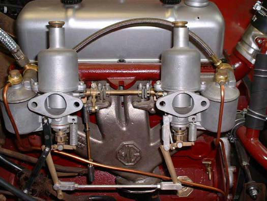
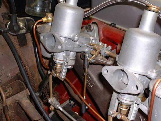
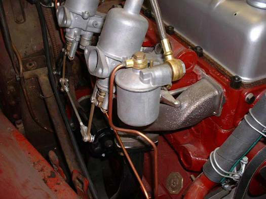
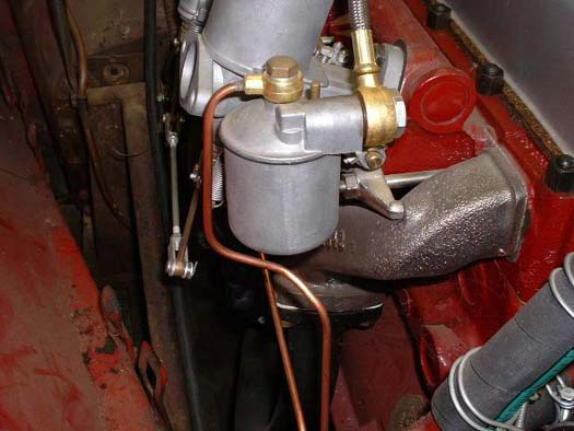
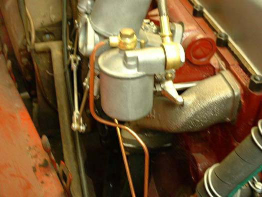
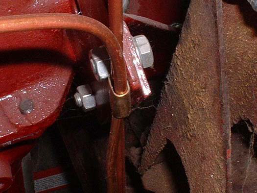
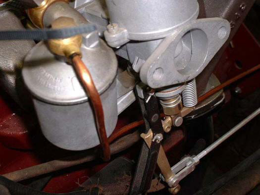
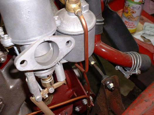
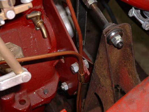
Question:What is the correct routing for the Carburettor overflow pipes please?
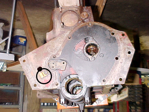 Reply: The overflow pipe(s) - there are two on a YT, should pass over the front engine plate and through a retaining bracket on the front of the front engine plate. See the picture right and double click on it to enlarge it. For a full set of photographs of the routings of the carburettor overflow pipes for the YT see the table below. The over flow pipe on the single carburettor on the Y/YB follows a similar route for any one interested. The picture (right) shows the bracket attached to the front of the engine front plate. This picture was taken of an engine that in all other respects was completely untouched. In our publication "Enjoying the MG Y Type", there is a complete picture flow of the manufacturing process of a Y Saloon. The complete engine was lowered onto the bare chassis before the body was fitted. However, after doing a decoke or any head work, refitting the pipes so as to pass through the clip on the front side, and the clamp bolt be tightened, would be a very time consuming process. The more usual position for this clamp therefore is for it to be found in a totally horizontal plane on the rear of the front plate or carburettor side.
 |
 |
 |
 |
 |
 |
 |
 |
 |
 |
 | |
![]()
Question: The speedometer needle swings wildly and I am not sure if it is cable or speedometer itself. Even on the bench (with an electric drill as power) and cable straight sped still swings too much.
Reply: The problem is not the cable. At least not yet!. The speedometer works by generating a electro magnetic flux which is what "powers" the head to give the reading on the dial. As, with time, the magnets in the head become worn, they become less effectual in generating a consistent flux or current. Other reasons could be gearbox oil is "climbing the cable" and oil has contaminated the head. It may also be that due to MIG welding, or other "earthing" problems the head is becoming seized and this will eventually seize the head and snap the cable at the gearbox end (See Hints and Tips on Speedometer cables). You must have a good condition earth strap between the gearbox bell housing and the chassis making a good connection at both ends. Please check this out (you will need to get under the car - passenger side in an RHD vehicle) for this. Renewing the earth cable, if perished will not cure the problem, but will prevent it from worsening due to this cause and should be done if you have the head rebuilt (for the want of a penny of tar, the ship was lost). As a result of any or all of the above, the needle will fluctuate wildly and you will have to "average" your speed! The answer is - a complete rebuild of the speedometer head is required. It is interesting to note that in 1965 a letter was sent to an owner of a YB that to PREVENT (not cure) this problem they were advised to fit a new speedometer cable. See the BMC Letter in Collectibles.
![]()
Question: Having had an oil leak from the rear offside wheel I have stripped it down to replace the oil seal. When doing this I see that no grease has been used in the bearing, it has been relying on oil from the differential coming down the half shaft for lubrication in a similar way that the TF which I have seems to. Would you recommend continuing with oil lubrication as it has been now for at least 8 years unknowingly, or should I change to grease which I assume was originally intended as there is a nipple on the end of the half shaft.
I have spoken to Jack Murray and he uses grease in his YA but I am reluctant to change something which has been working unless there is good reason.
Reply: The YA rear axle is a MORRIS axle, the one on the TF is a NUFFIELD rear axle is a hypoid type, the YA is a spiral-bevel type. Both use EP oil, extreme pressure, and both rely on splash lubrication of the outer rear bearing. It is indeed a grease nipple, but it will do no harm to oil the outer bearing. Use EP140 if you can find it. You will get really messy filling your grease gun with oil, but it can be done. Alternatively, you can use the original grease nipple.
![]()
Question: For some time now I have had an oil leak from the rear differential. At first it was minor and I lived with that. Now it is becoming more pronounced and it can only get worse. The NTG schematic for the rear axle could be better but I think what I need is part # G444Y. Am I correct? For the TC Moss has developed a differential pinion cap and modern double lipped oil seal. The rear axles etc. are the same basic design but different. Is there a modern seal that can be used on the Y in this application
Reply: The rear axle on the YT is identical to the TA, TB & TC, as well as the YA. It is a MORRIS type axle, (that on the YB & TD / TF is a NUFFIELD axle,) also found on the Morris 10 & 12hp, and identical Wolseley saloons, and lots of Morris Commercial vans. The seal you need is G444Y, and it is not too difficult to replace. The nut holding on the propeller shaft driving flange is VERY VERY tight, (about 120 lb/ft). Drill a bit of angle-iron to bolt onto the diff flange with two bolts, anchor the end of the angle iron on the floor, then heave that nut undone. With it off, the flange will pull out. Then you can see the neoprene seal. Flick it out with a screwdriver, and the CAREFULLY fit a new seal, ensuring it is lubricated, (or it will burn out).
Refit the flange, tighten up that big nut to 120 lb/ft, top up the diff oil, refit the prop-shaft. If the seal leaks again you may well have wear in the pinion bearings, permitting a little play. Such seals cannot cope with more that a few 'thou' play. A 'double edge seal' will not perform any better than a single spring loaded lip seal. They usually leak a little after about 10,000 miles. Later axles had a small shroud fitted to keep road dust away from the area.
NTG seals are expensive, the same can be had from the MG Octagon CC cheaper.
![]()
Question: I have started to overhaul my gearbox, (which I stripped about 2 years ago), & I have a question regarding 1st & 2nd sliding hub assembly. I have end float of .032" between the sliding hub assembly & the circlip on the mainshaft. (Item nos.42 & 45 in the Y type workshop manual). Is this normal? I ask because the bearing guard, (item no.23), would take up this space & appears to serve no useful purpose where it is!! (It is nearly the same size as the circlip although not as thick). Brown & Gammons parts book also show the circlip & bearing guard in the same position as the Y manual. Your thoughts would be most welcome.
Reply: The end float between the sliding hub assembly and the circlip should be within 0.004" and 0.008" (0.10 to 0.20 mm). When float is more, gears can jump out. It is possible to lower the clearance by shims of the right thickness. The world XPAG gearbox specialist had to be drafted into the Technical Team to handle this one. Thanks Bert, DAP.
![]()
Question: I am presently doing "paper" redesign of braking system for my YB, which is in bits, some big, some small on my garage floor! I have already purchased a stand alone servo and am now looking at possibility of MGB discs on the the front. In fact I have a scrap MGB front end. The bits will fit with a few modifications and shorter track rods, I will have to commit to 4-stud steel wheels and this brings me to a major snag, I need 9 inch rear drums, 4-stud, that will fit my [splined] Nuffield axle. As far as I know the Wolseley 4/44 could be a possibility except that I am not sure if 4/44 had splined Nuffield axle, everything else seems to fit the bill. Any body familiar with Wolseley 4/44s?
Reply: The Wolseley 4/44 NUFFIELD rear axle is identical to that of the YB, apart from the brake drum-cum-hubs having just four studs. Theses studs are spaced at the standard BMC distance, as used on the BMC banjo's rear axle on the MG Magnette ZA, ZB, Wolseley 15/50 and the Farina cars. This should mean MGB wheels will fit it easily, as they also use the BMC standard hubs. Other cars using the same rear axle as the YB are the Morris Oxford & Cowley range of MO series, though the spring pad width differs. These models also use the standard BMC hub's. Note some late 4/44's and 15/50's use the BMC banjo rear axle from the Farina range, as used on the 'Z' Magnettes.
![]()
Question: My YA brakes do not give me any confidence, whereas the purely mechanical system on my 1937 Austin Ruby seem much better. The YA has passed its Mot, all the brakes have been checked, and all adjusted according to the manual. The handbrake holds well.
Reply:The YA is of its age. It has a pre-war single-leading-shoe system fitted to all the wheels. This actually means only half of the shoes are working efficiently in any direction. The YB was fitted with twin-leading-shoe front brakes, which improved the forward braking a lot, but reduced the reverse braking available. As few people do 70mph in reverse, this was not important! Also, all the 'Y' series are very heavy cars for their engine size. Your A7 Ruby is a very light car. If your YA passes its Mot test on its brakes, with good efficiency on all wheels, there can be very little wrong with the system. Perhaps you need to push a lot harder on the direct-acting, non-servo, drum brakes? The leverage-ratio of the 'Y's brake pedal is not very high, none were in those days. Cross-ply tyres are also poor in grip compared to modern radial-ply, and this can effect braking in that they skid much easier in the wet.
If you still feel worried over the brakes, then every brake cylinder will need to be checked for correct working. Often in cars little used, the pistons will seize up in the slave cylinders. New seals can be obtained from people like the Octagon CC. Brake shoes need to all be of the same specification material, and not contaminated by any oil or grease leaking from a wheel bearing. The master cylinder can suffer from faulty seals, making it very stiff to operate. The brake and clutch pedal shaft can wear badly, and partially seize, modern replacement shafts have grease holes drilled right through them. New linings fitted into 'skimmed' drums will take ages to " bed-in" as the internal diameter of the drum will be too large.
Brake hose also need replacing quite often, as does the brake fluid. Hoses can break up inside and restrict the fluid flow. You push hard on the pedal, but the faulty hose cuts your foot-power by half, and the internal linings of theses hoses can even act as a non-return-valve, (causing the brakes to stick 'on'.)
The brakes are the same as the TC, but the TC is much, much, lighter.
The 'Y' handbrake is a separate system, and always has been an excellent design-far outstripping any modern cars. It is possible to lock up the rear wheels using just the handbrake.
![]()
Question: I am restoring a YB and am now attempting to rewire the vehicle. I have a new harness (3 pieces), a workshop manual, the David Lawrence Book and the Club Wiring notes. I am electrically "literate" but sadly at a loss. I have identified the main loom. The other 2 looms are not as easy. Many of the colours are not in agreement with the reference notes mentioned above. The loom came with no decode. Apart from a manual rewire using my Avo meter any other ideas?
Reply: There is nothing complicated about the wiring on a 50-year-old car so we can get through this one easily. I don't know where you acquired your loom from but there are a couple of variations. Let's identify the colours that the maker has used and assume that they are consistent throughout. I would suggest that you lay the loom out on the kitchen floor, the lounge is more comfortable but from personal experience wives are not always sympathetic to this.
You should have a main loom, a subsidiary loom and some wiring to connect the instruments behind the dash. I would suggest that you organise a few sticky labels and you can mark up the wires with their connection points i.e. Side lamps, Headlights, Brake switch, Dipswitch, Dynamo, Coil etc.
When you lay the loom(s) out on the floor you should be able to identify the headlamp and side lamp wires. The headlamps will usually be Blue/White (First Colour - Second Tracer) and Blue/Red. I have also seen wiring looms where they have used Red/black and Yellow/Blue. The side lamps are usually always red and the red ones at the back will also be sidelights. If you have had a wiring loom with additional wiring for indicators these are usually Green/Red and Green /White.
I assume that whoever has made the loom has fitted some of the connectors on, i.e. those for the Dynamo (usually Yellow & Yellow/Green) the dipswitch (two of the three wires should match those that you have identified as headlights).
Once you have established the front and the back then it should be relatively easy to work out the rest by the position of the wires. The fog lamp will come out of the loom between the two headlamp wires, the horn wire will also come out at roughly the same place. The Trafficators wires will come out halfway down the car and the Brake light switch will be nearer the front. The brake light switch will be the same colour as one of the extra wires you have at the rear once you have accounted for the rear lights (usually red), the additional indicator wiring (if you have them fitted). The other wire that isn't the brake light is the reversing light.
The only difficult (relatively speaking) is the connection of the regulator. This is where the two looms connect. Again it would be good to identify the colours used but normally the ammeter wire can be identified because it is obviously thicker than the others. It is usually Brown with a white tracer. The Earth connections at the Regulator and elsewhere are usually Black. Ignition wiring is usually white.
Once you have identified some of the colours (Headlamps) please give me a ring or sent me an E-mail and I will try and find a wiring diagram to match. Failing this we can continue this exercise and find where each wire goes to.
Update: 1 January 2022 Back in 1985, David Ransome (former owner/operator of Whyparts) produced a very simple guide to assist in doing this job and here are his notes.
![]()
Question: As you are aware, I am restoring YB 0279. My question concerns changing the brushes on my dynamo. The ref no on my dynamo is C39PV2 LO but it has no cover plate to access the brushes as shown in the workshop manual. It appears that I have to remove the whole end plate to gain access. If this is the case are their any pitfalls to be aware of?
Reply: You have a later type dynamo, but that does not matter. The end plate comes off when the two full-length screws are undone. Pull the plate away and lots of filthy black soot will fall out, this is the remains of the old brushes. Clean everything up with carburettor cleaner, then replace the worn brushes with two new ones. Note how the little coil springs locate of the brushes, and where and what electrically screws to what. Assemble the dynamo, then put on the rear plate, whilst holding the brushes well up into their housings. This is best done by letting the brushes stick out of the top of their slides, and with the coil spring lifted off the top and placed to one side, so gripping the brush. Once the end cap is located over the commutator, (now nice and clean,) release the springs. Screw up the cap. Oil the bearings very sparsely, as if it gets on the brushes it ruins them. Check the brushes are seating on the commutator properly, and fit the dynamo to the engine.
![]()
Question: I was wondering if any of the Y owners out there who have taken their cars on trips to the continent (Europe) have made up a comprehensive list of spares and things to take (for the car of course). I am contemplating a trip this year and although I have made a list of some obvious items there may be some I haven't thought of.
Reply:I do not think that anybody has put together a 'recommended' list. I have taken my Y over on the continent several times to France, Holland, Germany & Luxembourg. I list below things that I would recommend:
- RAC Get you home cover - This is taking the most pessimistic view first. This cover is usually given free with most Classic car insurance policies.
- Then down to the actual Bits & Pieces - Probably the most important - a spare half shaft.
- Fan Belt and Hoses.
- A set of spark plugs, condenser, HT leads, distributor cap, points (contact breakers), and at least one plug cap. (If you have a spare coil it is also worth taking.)
- A selection of coreplugs - Both the large and the small ones.
- Regulator and dynamo (or at least bushes)
- Float(s) for carburettor.
- Some spare wire and insulating tape.
- A pair of jump leads.
- A battery charger with a European adaptor plug.
- A wire coat hanger can solve all sorts of problems.
- Make sure that your Spare Wheel is inflated to the correct pressure before you leave. If you have not taken the wheel out in a long time, get it out to check,
- that you can get it out,
- check the condition of the walls of the tyre, and,
- its ability to hold pressure. If the walls of the tyre are perished, renew it before you go.
- Spare lighting bulbs.
- A warning triangle (This is obligatory in most European Countries)
- Telephone numbers of Brown & Gammons, NTG and Moss. (All of them send parts to Europe on a next day delivery). On the trip to Brittany in 2002, Brown & Gammons sent some parts to a broken down YB (rocker pillar) and we managed to get it going again. A rocker shaft is also useful if you have one.
- A spare key, to be left in the battery box, perhaps tape it to the inside. You will never find a MRN key on the continent.
- The workshop manual - even if you do not speak the language the data may be useful (a calculator and conversion table for weights and measurements - feet and inches into centimetres, volumes, etc will also be invaluable).
- A lead light - 12 Volt, and a torch too (in case you breakdown at night).
- Your credit card.
- Finally any other spare part that you have that will not take up much room.
It is important to remember that whatever you take will probably be a guarantee that you won't need it. However, I think that the above should not take up too much extra space and should protect you against the normal (with 50 year old car) problems. A fire extinguisher is also now mandatory in some European countries, also in some 2 warning triangles are mandatory. Drivers should check with their motoring organisation well before setting off for idiosyncrasies and requirements of the countries they are travelling too.
![]()
Question: I have had a gearbox problem for years: the 3rd gear is always jumping out on down hill sections or when changing down from 4th to 3rd gear. Some time ago I replaced part of innards (third gear and matching lay gear as well as all bearings, rollers, shafts and claws etc). All in vain - the result was NIL. At the moment the gearbox is out of the car again. Your recent article about the end float of 1st and 2nd gear gives me hope. Could you please draft Bert again, the world's XPAG gearbox specialist? Any hints about fixing this third gear problem are appreciated.
Reply: (From Bert our XPAG Gearbox Expert) There are three possible causes for the problem of jumping out of gear. This applies for all the gears. You have to bear in mind that when going downhill or braking on the motor, the forces in the gearbox are opposite to those when driving normally forwards. So when there is no play when driving normally, there is maximum play when braking on the motor.
- The balls and springs in the striking dog/sliding hub are too weak, so that the striking dog is not held in place on the sliding hub. (Usually this is not the cause).
- The balls and springs on the shifter shaft are too weak. (Sometimes, this is the cause).
- There is play axially between the gears on the mainshaft. This is the play mentioned in the previous answer by jumping out of second gear. With the gearbox put together and the top cover removed, you can feel(and measure) the play. The play for all gears must be within 0.1 and 0.2 mm (0.004 and 0.008 inch). If it is more, you have to reduce it by using shims of the appropriate thickness. This is the most common cause for jumping out of gear.
![]()
Question: Are radials available yet in the size for theYB?
Reply: The YB wheel size is identical to the VW Beetle, so radial ply tyres are plentiful. BUT they are too wide for the spare wheel lid. Owners who use radial's deflate them to put the spare in the spare wheel tray, and carry a foot pump to re-inflate it (cross-ply tyres are 'thinner' in section than radials of the same size).
![]()
Question: As the owner of a recently purchased 1950 Y Type, # 4629 I think! I have been trying to determine the weight of the car for trailers. Could you help me out with the weight of the car?
Reply: With no fuel, but all oils, the car was 21cwt, that is 2,300 English pounds.
![]()
Question: We want to add full front and rear turn signals as well as having the trafficators function at the same time. We would like some suggestions on doing this transformation?
Reply: You cannot have flashing indicators and semaphores on the same circuit, UNLESS you wire them up using relays to operate each separate system. You will have to use the steering wheel switch to operate two systems via relays because the wiring in the steering wheel cannot take the current used by flashers. It is not difficult, as you just leave the present semaphore system as it is, but run a wire to a relay to operate a flasher unit for each side of the car. You may like to consider the option of fitting dual filament bulbs to the 1130 sidelights. These are available from Woolies, Gregory Autospares and many of the other Lucas replacement suppliers. This is neat and avoids the need to fit additional flashers to the front of the car. With the back I think that you should fit orange indicators, mounted on a bracket that itself fits on to the bumper iron connections to the chassis. This avoids drilling any extra holes in the body work. If you purchase Y Datasheet 3, this is covered in full, together with a wiring diagram revision. This is available from the MG Car Club Y Type Register shop - see Links Page and Clubs for their link.
![]()
Question: I have just replaced the timing chain and sprockets. The question that I am now pondering over is which is the correct orientation of the crankshaft and camshaft oil throwers. Various books and w/s manuals seem to contain conflicting or ambiguous information and I do not have high confidence in the previous assembly being correct. Is the following correct?
Reply:
- There is no oil thrower on the camshaft, it is just a washer, and its concaved face goes towards the cam.
- The oil thrower on the crankshaft faces forwards, that is the concaved face faces the fan belt pulley. It actually curves around the fan pulley end, to 'throw' oil away from the area. It is not vital as it still works the other way, but not as well.
Only shafts that 'exit' the engine have oil throwers fitted. The camshaft is totally enclosed so does not use one.
![]()
Question: I am currently carrying out some restoration work to my YB (Register no. 5567) and I have had the boot lid re-skinned. The boot seal was ill-fitting and was quite obviously not the right seal for the car so I removed it. When I looked in the parts catalogue I noted that two boot seals are listed, one 62 inches in length and the other 34 inches in length. The rim of the channel surrounding the boot aperture has a lip along the top and down each side but there is no lip on the bottom section so I presume that accounts for the 2 different types of seal.
Please could you advise if there is a significant difference between the 2 seals and is it still possible to buy the correct seals or is it simply a matter of finding a suitable boot seal that will fit in the channel on all 4 sides of the boot aperture?
Reply:
Neil Cairns: - My YB only has a seal on the top and two sides, stuck to the boot lid. It is a square section runner sponge. There is no seal on the bottom edge on my car, it seems to rely on the 'gutter' formed by the boot aperture.
David Pelham: - On both my YA & YT I have a continuous seal going round the two sides and top of the boot aperture. This was a conscious decision not to fit the seal to the bottom (see my Hint & Tip) as if you have a seal here the water will not disperse and it will rot (Just like the original). My boot seal is a square section that I believe I bought from Woolies or possibly East Kent Trimming. NTG sell the seal, I believe their number is R237 and they use the same part for both the boot and the spare wheel cover. Again don't fit the seal to the bottom of the spare wheel cover - let the water disperse.
![]()
Question: My car is currently running with it's original engine - i.e. not converted to lead free. At this moment I can't buy leaded petrol or petrol with an additive. What must I do? Can I tank 100 oc. petrol mixed with the lead replacement that we can buy? Can give this damage my engine? Or must I change other things?
Reply: If you run the car at about 50 to 60kph, you will probably not do very much damage to the exhaust valve seats. If you drive faster for long runs, you will burn out the valve seats eventually. The cure is to have hardened steel valve seats fitted to the exhaust valve ports. There are a few UK MG specialists who will do this on an exchange basis, (i.e., swapping your cylinder head for one already modified.) Or you can buy petrol additive to make up for the missing TET, 'VALVEMASTER' is one type sold.
![]()
Question: I've noticed that the choke cable on my car seems very stiff. I tried squirting some WD40 onto the bottom end of the cable, but it doesn't seem to have made any difference. Can you offer any suggestions?
Reply: The choke cable is a single large strand, like a wire. It is made to PUSH and PULL the choke tube, and has a friction device inside the dash-board end. The cable can get very dry, and sometimes rust a little, if not used. To improve the working of the cable, undo the carburettor end, pull out the inner-cable from the dash, oil it well and re-insert it into the dash. Re-fit the carburettor end and adjust as required. Squirt some oil down the outer cable via the dash end, before re-inserting the inner cable. If you have a clutch cable made of many strands (like a bicycle brake cable) buy a new 'proper' choke cable
![]()